3
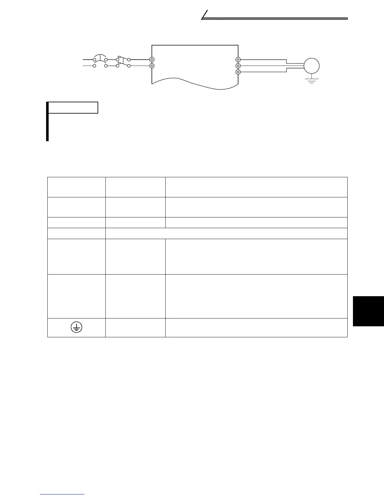
Standard connection diagram and terminal specifications
1
WIRING
Single-phase 100V power input
1.1.2 Explanation of main circuit terminals
(1) Main circuit
REMARKS
•To ensure safety, connect the power input to the inverter via a magnetic contactor and earth leakage
circuit breaker or no-fuse breaker, and use the magnetic contactor to switch power on-off.
•The output is three-phase 200V.
Terminal
Symbol
Terminal Name Description
R/L1, S/L2,
T/L3 (*1)
AC power input
Connect to the commercial power supply.
U, V, W Inverter output
Connect a three-phase squirrel-cage motor.
PR (*2)
Do not use PR terminal.
P/+, N/−
Brake unit
connection
Connect the brake unit (BU), power regeneration
common converter (FR-CV) or high power factor
converter (FR-HC). (The N/- terminal is not provided for
the FR-S520E-0.1K to 0.75K-NA.)
P/+, P1
Power factor
improving DC
reactor
connection
Remove the jumper across terminals P - P1 and connect
the optional power factor improving DC reactor (FR-
BEL(-H)).
(The single-phase 100V power input model cannot be
connected.)
Ground For grounding the inverter chassis. Must be grounded.
*1. When using single-phase power input, terminals are R/L1 and S/L2.
*2. The PR terminal is provided for the FR-S520E-0.4K to 3.7K-NA.
NFB
IM
U
V
W
MC
Power
supply
Motor
Ground
S/L
2
R/L1

 Loading...


