31
Input terminals
1
WIRING
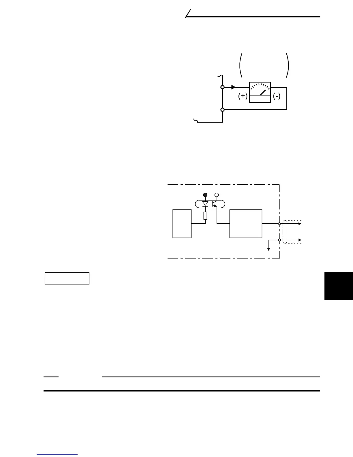
1.4.4 Indicator connection and adjustment (AM)
A full-scale 5VDC analog signal can
be output from across terminals AM-
5.
The analog output level can be
calibrated by the operation panel or
parameter unit (FR-PU04). Terminal
AM function selection can be set in
Pr. 54 "AM terminal function
selection".
Terminal AM is isolated from the
control circuit of the inverter. The
cable length should not exceed
30m.
The output signal from terminal AM
delays about several 100ms in
output and therefore cannot be used
as a signal for control which requires
fast response.
Terminal AM Output Circuit
Set the reference output value of the inverter which outputs the full-scale voltage
5VDC.
Set it in Pr. 55 for frequency monitoring reference, or in Pr. 56 for current monitoring
reference.
Use the terminal AM output calibration parameter C1 to adjust the output voltage.
[Example] 1. To set the output across AM-5 to 5VDC at the inverter output
frequency of 90Hz, set 90Hz in Pr. 55. (Factory setting: 50Hz)
2. To set the output across AM-5 to 5VDC at the inverter output current of
20A, set 20A in Pr. 56. (Factory setting: rated inverter current)
CAUTION
•Refer to page 126 for the procedure of indicator adjustment.
AM
5
Meter
5V full scale
Analog meter
CPU
AM
5
5VDC
Inverter
AM
circuit
Adjustment

 Loading...


