3-51 Emergency stop input and output etc.
3 Controller
Be sufficiently careful and wiring so that two or more emergency stop switches work
independently. Don't function only on AND conditions (Two or more emergency stop
switch status are all ON).
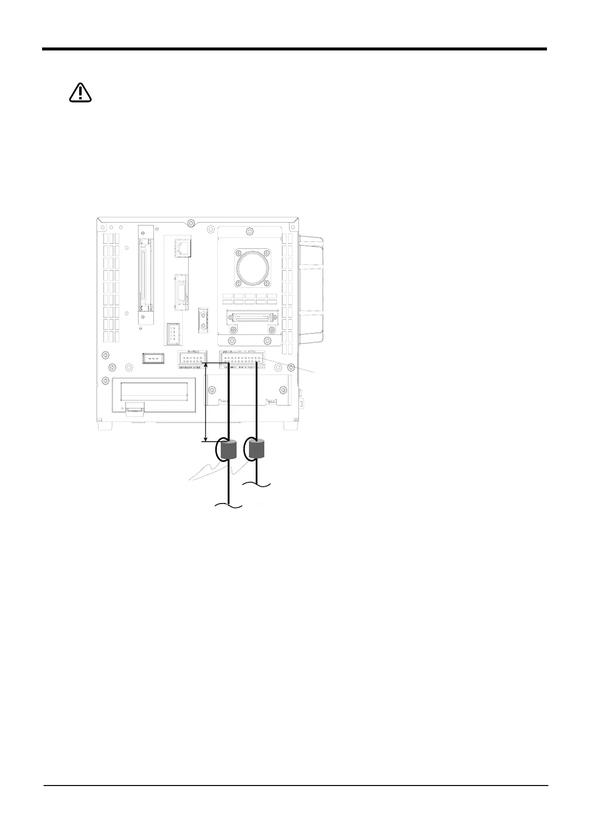
Fig.3-12 : Emergency stop cable connection (ferrite core installation CR1DA-700 series)
CAUTION
EMGINコネクタ
300mm以内
フェライトコア(付属品)
2回通し
外部装置からの非常停止入力信号線
外部装置への非常停止出力信号線
<CR1DA-700 series>
Pin allotment of EMGIN and the EMGOUT connector is shown in Fig. 3-13.
Within 300mm
EMGIN
The emergency-stop-input line from external equipment
The emergency-stop-output line to external equipment
Ferrite core
(attachments)
Pass twice
* The figure is standard specification
controller.
(CE marking specification is the same.)
Note) Install one ferrite core on the emergency
stop line of both of the input-signal and
output-signal between peripheral
equipment each. However, when wiring by
the input/output signal line is bundled,
install two ferrite cores on the bundled
line.
 Loading...


