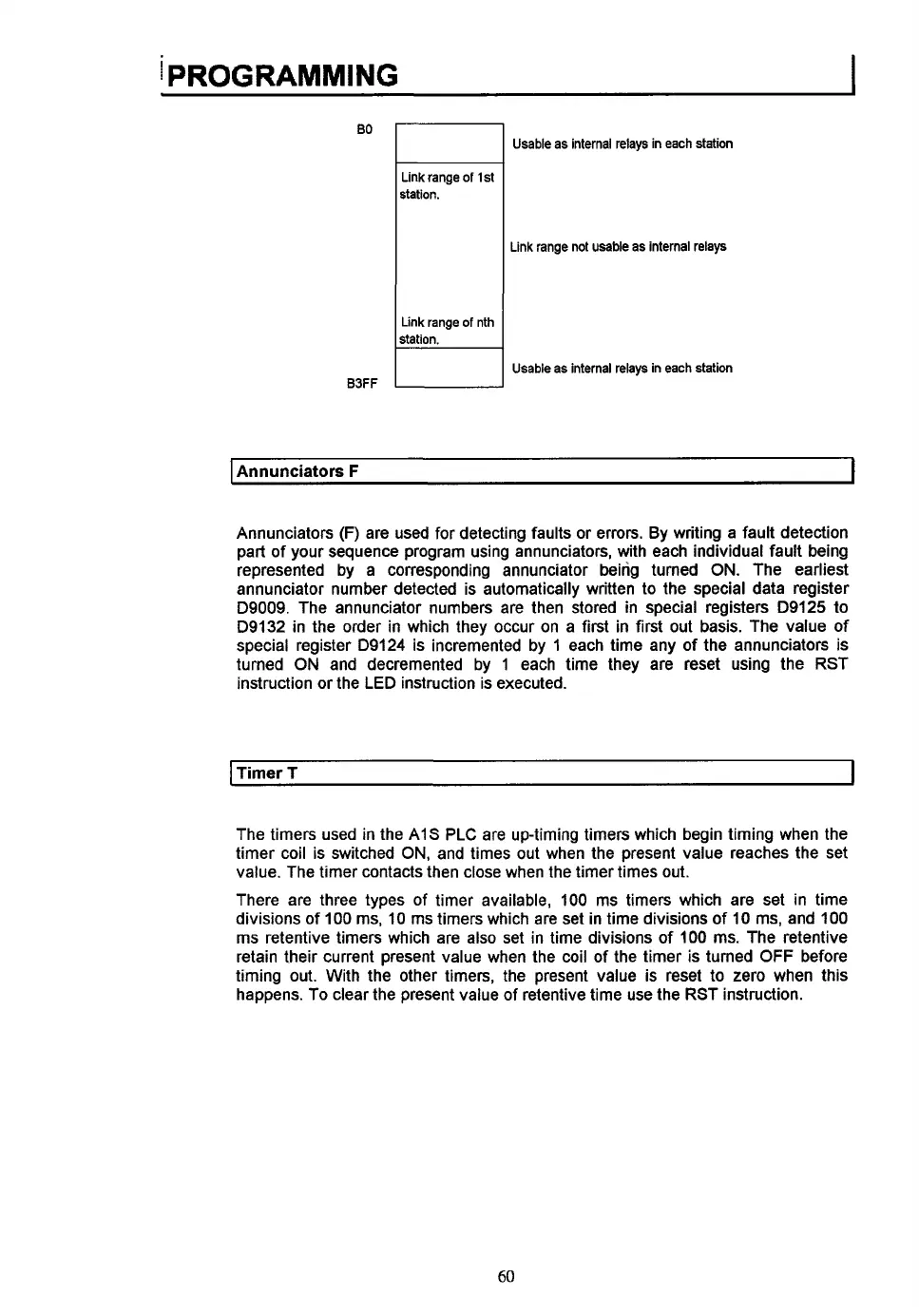
EasyManua.ls Logo

Mitsubishi MELSEC A1S61P User Manual

Mitsubishi MELSEC A1S61P
149 pages
To Next Page IconTo Next Page
To Previous Page IconTo Previous Page
Page #66 background imageLoading...
Page #66 background image
I
PROGRAMMING
Bo
I
I
Link range
of
1
st
station.
Link range
of
nth
B3FF
I
Usable as internal relays in each station
Link range not usable as internal relays
Usable
as
internal relays in each station
I
Annunciators
F
I
Annunciators
(F)
are used for detecting faults or errors. By writing a fault detection
part of your sequence program using annunciators, with each individual fault being
represented by a corresponding annunciator being turned
ON.
The earliest
annunciator number detected is automatically written
to
the special data register
D9009. The annunciator numbers are then stored in special registers D9125
to
D9132 in the order in which they occur on a first in first
out
basis. The value of
special register D9124 is incremented by 1 each time any of the annunciators is
turned
ON
and decremented by
1
each time they are reset using the RST
instruction or the LED instruction is executed.
I
Timer T
I
The timers used in the AIS
PLC
are up-timing timers which begin timing when the
timer coil is switched
ON,
and times
out
when the present value reaches the set
value. The timer contacts then close when the timer times
out.
There are three types of timer available,
100
ms timers which are set in time
divisions of
100
ms, 10 ms timers which are set in time divisions of
10
ms, and 100
ms retentive timers which are also set in time divisions of
100 ms. The retentive
retain their current present value when the coil of the timer
is
turned
OFF
before
timing out. With the other timers, the present value is reset to zero when this
happens. To clear the present value of retentive time use the RST instruction.
60

Table of Contents

Question and Answer IconNeed help?

Do you have a question about the Mitsubishi MELSEC A1S61P and is the answer not in the manual?

Mitsubishi MELSEC A1S61P Specifications

General IconGeneral
CategoryController
SeriesMELSEC A
ModelA1S61P
Input Frequency50/60 Hz
Output Voltage24 V DC
Number of Inputs32
MountingDIN Rail
Applicable PLCMELSEC A Series
CommunicationRS-232

Summary

Chapter 1: Overview of the A1S PLC

What is the A1S?

Describes the Mitsubishi A1S PLC as a low cost, high performance, compact micro modular PLC.

How Does It Work?

Explains the PLC's sequential operation, input/output updates, and memory structure.

Chapter 2: AIS Module Descriptions

CPU Module Details

Details the core processing unit of the A1S PLC system, including its function and specifications.

CPU Base Units

Describes base units for mounting CPU, power supply, and I/O modules, detailing different models.

Extension Base Units

Explains extension base units for additional I/O modules and power supply slots, listing models.

Power Supply Modules

Details the function and models of power supply modules that provide 5 VDC for system operation.

Input Modules

Covers various input modules, detailing their specifications, connections, and current consumption.

Special Function Modules

Describes intelligent I/O modules for specific applications like positioning, linking, and networking.

Output Modules

Details various output modules, their specifications, connections, and current consumption.

Chapter 3: System Selection and Configuration

Input Module Selection

Guides the user through selecting the appropriate input modules based on technical specifications.

Output Module Selection

Guides the user through selecting the appropriate output modules based on technical specifications.

Power Supply Module Selection

Guides the user in selecting the correct power supply module based on system voltage and current needs.

Base Unit Selection

Guides the user in selecting the appropriate base unit based on the number of required I/O slots.

Chapter 4: Installation

Chapter 5: Wiring

Power Supply Module Wiring

Provides guidelines for wiring power supply modules, including transformers and noise reduction.

Chapter 6: Programming

Internal Device Descriptions

Explains internal devices like inputs, outputs, relays, timers, counters, and registers used in programming.

Related product manuals