lwiring
of
110
equipment
I
Below are wiring instructions for equipment connected
to
the input and output
modules of the
AIS system.
1.
The applicable size of the terminal block connector is
0.75
mm2 (AWG
18)
to
1.5
mm2 (AWG 14). However, it is recommended to use the smaller size
cable as
it
is more convenient to use.
2.
Separate the input and output lines.
3.
I10
signal wires must be at least
100
mm/3.94 in. away from high voltage
or
high current main circuit wires.
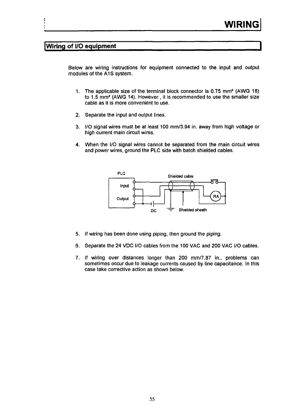
4.
When the
I/O
signal wires cannot be separated from the main circuit wires
and power wires, ground the PLC side with batch shielded cables.
Shielded cable
PLC
Input
output
-
Dc
*
Shielded sheath
5. If wiring has been done using piping, then ground the piping.
6.
Separate the 24 WDC
110
cables from the
100
WAC and
200
WAC
I/O
cables.
7.
If wiring over distances longer than
200
mm17.87 in., problems can
sometimes occur due to leakage currents caused by line capacitance. In this
case take corrective action as shown below.
55
 Loading...