(C)
Instruction symbol
Indicates the instruction symbol used for the program. The instruction symbol is
shown on a 16 bit instruction basis, the symbols of a
32
bit instruction and
instructions which are only executed by a the rising edge from OFF
to
ON
are
indicated as below.
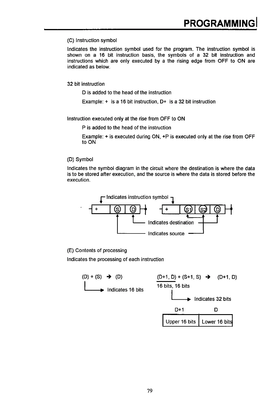
Upper 16 bits
32
bit instruction
D
is
added to the head
of
the instruction
Example:
+ is a 16 bit instruction,
D+
is a
32
bit instruction
Lower 16 bit
Instruction executed only at the rise from OFF
to
ON
P
is added
to
the head of the instruction
Example:
+
is executed during ON,
+P
is executed only at the rise from OFF
to
ON
(D)
Symbol
Indicates the symbol diagram in the circuit where the destination is where the data
is to be stored after execution, and the source is where the data is stored before the
execution.
1
Indicates instruction symbol
4-
+
Indicates destination
Indicates source
(E)
Contents of processing
Indicates the processing of each instruction
(D+1,
D) +
(S+I,
S)
++
(D+I,
D)
16 bits, 16 bits
I
Indicates 16 bits
k
Indicates
32
bits
D+
1
D
79
 Loading...