-
18
-
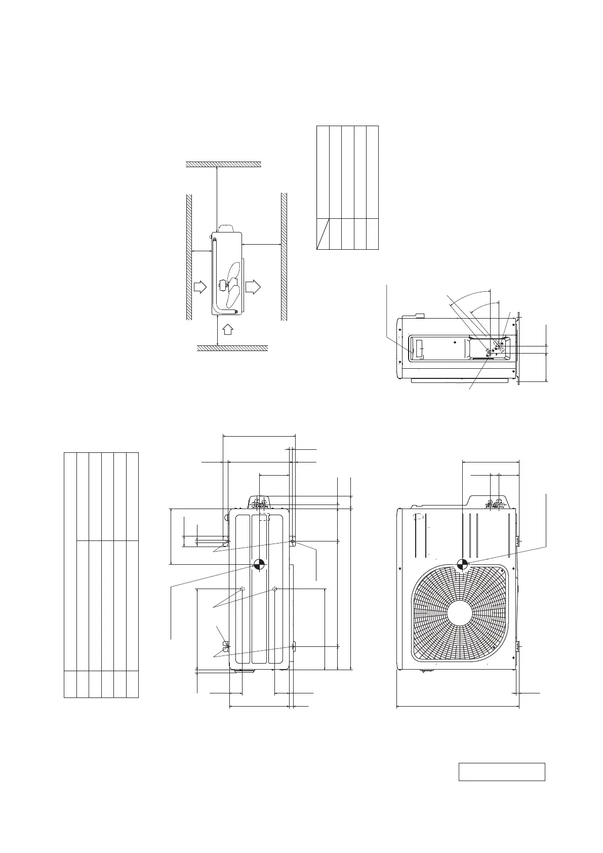
'18 • SRK-T-250
Unit:mm
2-12×16
Slot hole
2-R
φ12.7(1/2")(Flare)
Content
C Pipe/cable draw-out hole
D
E Anchor bolt hole
Drain discharge hole
Symbol
B
A Service valve connection(gas side)
M10-12×4 places
φ20×2 places
Service valve connection(liquid side)
φ6.35(1/4")(Flare)
L2
Inlet
Outlet
Inlet
L3
L1
Service
space
( )
L4
L2
L3
L4
L1
100 or more
80 or more
250 or more
280 or more
Installation space
63.4
390.6
390.6
111.6 510 158.4
780 61.9
17.9
14.8 312.5 24.3
351.6
50.6
12
29020
14.6
16.4
145
270
Terminal block
97.7 42.5
15.8
595
275
40°
40°
138.4 33.5
Center of gravity
69.4
Center of gravity
Notes
(1) The unit must not be surrounded by walls on the four sides.
(2) The unit must be fixed with anchor bolts. An anchor bolt must not
protrude more than 15mm.
(3) If the unit is installed in the location where there is a possibility of
strong winds, place the unit such that the direction of air from the
outlet gets perpendicular to the wind direction.
(4) Leave 200mm or more space above the unit.
(5) The wall height on the outlet side should be 1200mm or less.
(6) The model name label is attached on the right side of the unit.
C
B
A
EDE
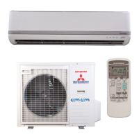
Model SRC50ZS-W
RCV000Z037
 Loading...