AP-5131 Access Point: Installation Guide
12
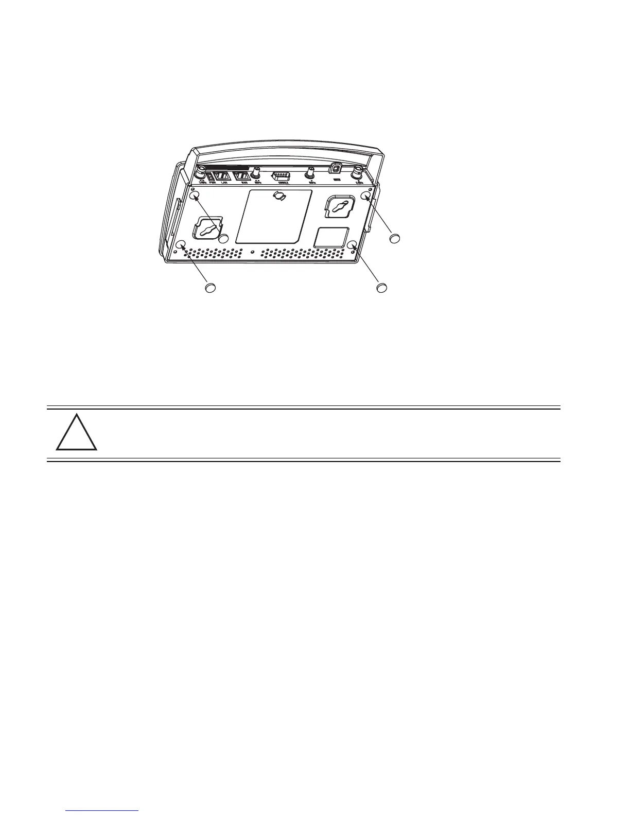
3. Attach the Radio 1 and/or Radio 2 antennas to their correct connectors. The antenna covers
will most likely need to be removed to orient the antenna upward in a typical desktop
installation.
For information on the antennas available to the AP-5131, see
“
AP-5131 Antenna Options” on page 6.
4. Cable the AP-5131 using either the Motorola Power Injector solution or an approved line
cord and power supply.
For Motorola Power Injector installations:
a. Connect a RJ-45 Ethernet cable between the network data supply (host) and the Power
Injector Data In connector.
b. Connect a RJ-45 Ethernet cable between the Power Injector Data & Power Out
connector and the AP-5131 LAN port.
c. Ensure the cable length from the Ethernet source (host) to the Power Injector and
AP-5131 does not exceed 100 meters (333 ft). The Power Injector has no On/Off power
switch. The Power Injector receives power as soon as AC power is applied. For more
information on using the Power Injector, see “
Power Injector System” on page 8.
For standard power adapter (non Power Injector) and line cord installations:
a. Connect a RJ-45 Ethernet cable between the network data supply (host) and the AP-5131
LAN port.
CAUTION Ensure you are placing the antennas on the correct connectors
(depending on your single or dual-radio model and frequency used) to
ensure the successful operation of the AP-5131.
!
72-70931_01.book Page 12 Monday, May 4, 2009 8:10 AM

 Loading...