Hardware Installation
11
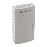
The Power Injector demonstrates the following LED behavior under normal and/or problematic
operating conditions:
For more information and device specifications for the Power Injector, refer to the Power Injector
Quick Install Guide (Part No. # 72-99410-01) available from the Motorola Web site, at
http://support.symbol.com/support/product/manuals.do
.
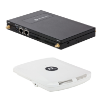
3.4 Mounting the AP-5131
The AP-5131 can rest on a flat surface, attach to a wall, mount under a suspended T-Bar or above a
ceiling (plenum or attic). Choose one of the following mounting options based on the physical
environment of the coverage area. Do not mount the AP-5131 in a location that has not been
approved in a site survey.
3.4.1 Desk Mounting
The desk mount option uses rubber feet (found in the accessories bag shipped with the AP-5131)
allowing the unit to sit on most flat surfaces.
To install the AP-5131 in a desk mount orientation:
1. Turn the AP-5131 upside down.
2. Remove the backings from the four (4) rubber feet and attach them to the four rubber feet
recess areas on the AP-5131.
LED AC (Main) Port
Green (Steady) Power Injector is receiving
power from AC outlet
Indicates a device is
connected to the
Power Injector’s outgoing
Data & Power cable
Green (Blinking) Output voltage source is out
of range
The Power Injector is
overloaded or has a
short circuit
72-70931_01.book Page 11 Monday, May 4, 2009 8:10 AM

 Loading...