Motortronics
- 6 -
XLS Series Solid State Soft Starter 39 - 1250A
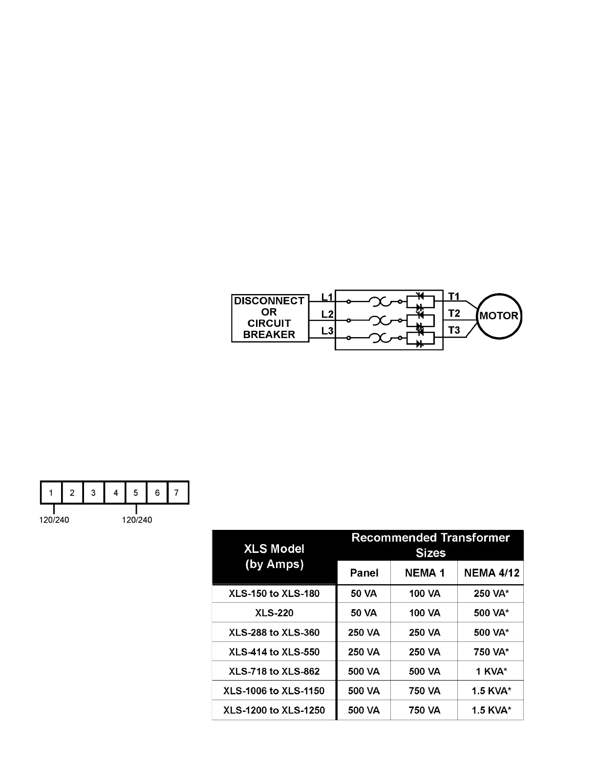
4.1 Power Connections
Connect appropriate power lines to the unit input terminals marked L1, L2,
L3. Avoid routing power wires near the control board. Connect the motor
leads to the unit terminals marked T1, T2, T3. Refer to NEC standards for wire
length and sizing. Never interchange input and output connections to the unit.
This could cause excessive voltage in the control logic circuit and may damage
the unit.
Note:
Never connect power factor correction capacitors on
the load side of the unit. The SCRs will be seriously damaged if
capacitors are located on the load side. The unit cannot be tested without
a motor or other test load connected to the load side of the unit. It may be
necessary to use a load bank to test the unit without a motor. Note that line
voltage will appear across the output terminals if there is no motor or load
connected to the unit. In areas where lightning is a significant problem, station-
type air gap lightning arrestors should be considered and utilized on the input
power source.
Note:
Some units may have the overload on the load side of the starter.
4.1.1 Grounding
Connect the ground cable to the ground terminal as labeled on the unit. Refer
to the National Electrical Code for the proper ground wire sizing and be sure
that the ground connector is connected to earth ground.
4.2 Control Connections
4.2.1 Control Power Connections
Separate 120VAC supply is required (240VAC for 380V and 415V applications).
The control voltage should be connected to pins 1 and 6 of TB1. This control
voltage must be customer supplied, unless an optional control power
transformer (See chart) has been supplied with the unit. On units rated below
100 HP, the TB1 terminal block is located on the main control board.
Power Connections
XLS Series Unit
TB1
Chapter 4 - Connections
Recommended Transformer Sizes for Control Power
Note: If power is used for
additional accessory items
(Lights, fans, etc.) contact factory
for sizing.
 Loading...