7
Electrical Connections
Page 33 mrcool.com
TO INDOO UNIT
115
POWER SUPPLY
Y/G
RED
32 L N1
3
21
WHITE
BLACK
L N
OUTDOO UNIT TE MIN L
TO INDOO UNIT
208/ 230
POWER SUPPLY
Y/G
RED
32 L1L21
3
21
WHITE
BLACK
L1 L2
OUTDOO UNIT TE MIN L
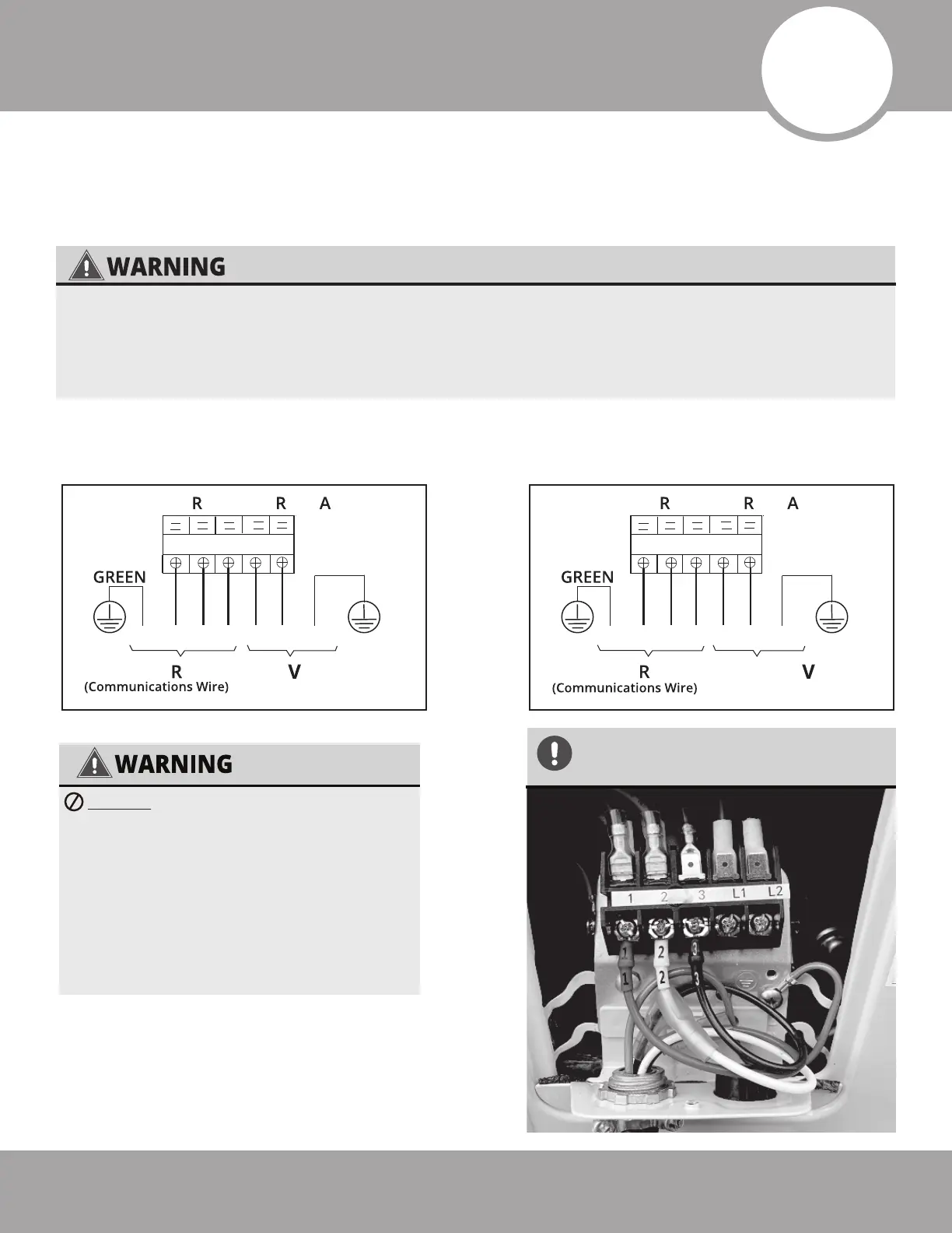
Fig. 7.1
WIRE CONNECTING DIAGRAM (12K Unit Only)
WIRE CONNECTING DIAGRAM (All other units)
Connect the MC Cable/signal wire and power cable
NOTE: The outside unit’s terminal block is protected by an electrical wiring cover on the side of the
unit. A comprehensive wiring diagram is printed on the inside of the wiring cover.
WIRES AND TERMINALS ARE NUMBERED
TO CORRESPOND WITH ONE ANOTHER
AS SHOWN BELOW.
***BEFORE PERFORMING ANY ELECTRICAL WORK, TURN OFF ALL POWER TO THE SYSTEM.***
Note that the wire colors of this series/model may differ from previous models, other series and
general wiring conventions. All wiring must be performed in accordance with the wiring
diagrams shown in Fig. 7.1 and demonstrated in the images below.
DO NOT MIX UP LIVE AND NULL WIRES.
• This is dangerous and could cause the
unit to malfunction. Make sure you
clearly distinguish the live (”L”) wires
from the other wires.
• All wiring must be performed in
accordance with the wiring diagrams
shown in Fig. 7.1 and demonstrated in
the images shown here.
 Loading...