Page 20mrcool.com
Unit Installation
Pipe diameter (in. | mm) Tightening torque (N·m)
Ф1/4” | Ф6.4
Ф3/8 | Ф8.3
Ф1/2” | Ф12.7
Ф5/8” | Ф15.9
Ф3/4” | Ф19
Ф7/8” | Ф22.2
15-30
35-40
45-50
60-65
70-75
80-85
DO NOT USE EXCESSIVE TORQUE
Excessive force can break the nut or damage
the refrigerant piping. You must not exceed
torque requirements shown in the table.
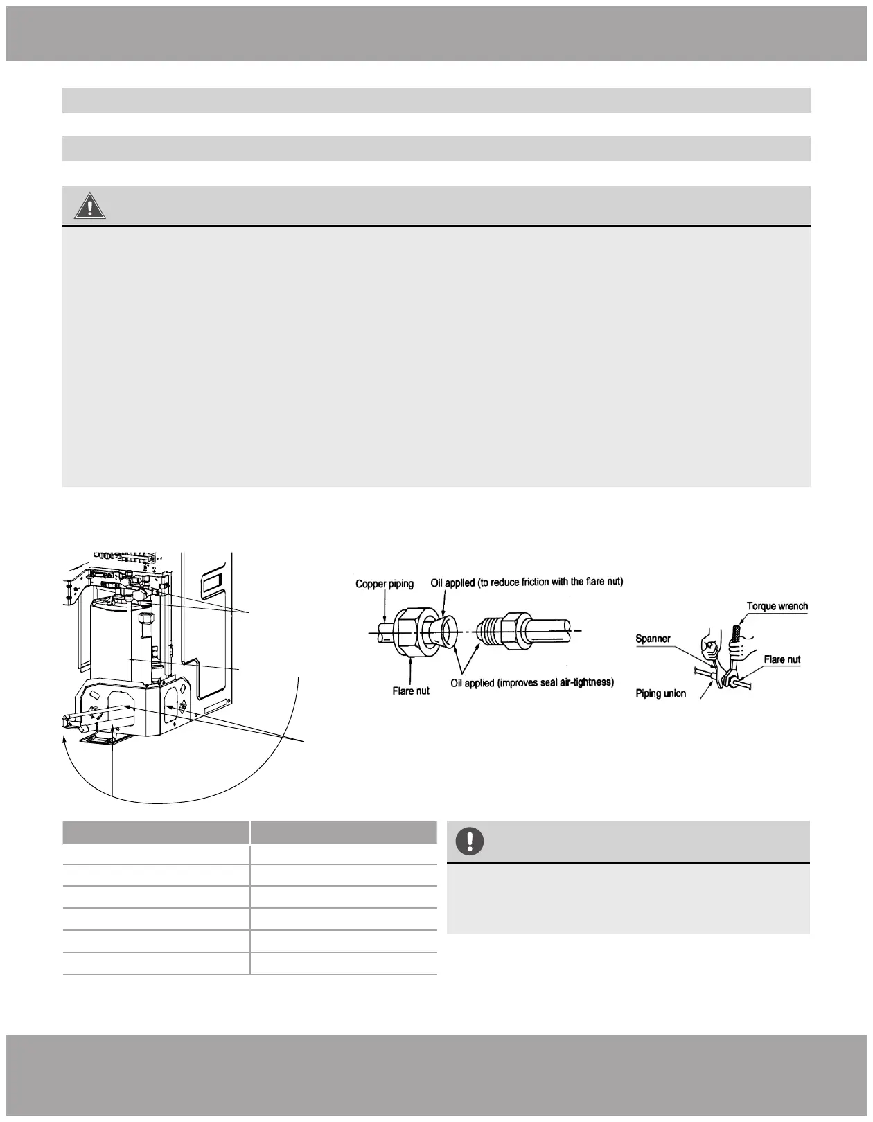
1. Screw on the flare nut of the flared connecting pipe onto the outdoor unit valve. Refer to Fig. 2.19 & Fig.
2.20,
using the torque values in the table below.
2. On Model MDUO18024036 plug the knockout holes shown in Fig. 2 .19A
with cotton to prevent small animals and debris from entering the unit.
Fig. 2.19B
Fig. 2.19A
Refrigerant Line Set
Connection Pipes
Cut Off Valve
Knockout Holes
WARNING
Connect the pipe to the unit. Follow all instructions below. Use both spanner and torque wrench.
When connecting the tapered screw nut, first apply chilled machine oil on its inner and outer
surface and then screw it on 3 or 4 threads.
Confirm the tightening torque by referring to the following table. If the screw nut is over-twisted,
it may be damaged and cause leakage.
Check whether gas leakage is occuring and then apply thermal insulation.
Wind sponge around the joint of gas pipe and heat insulation sheath of gas collecting pipe.
Be sure to connect gas pipe after liquid pipe is connected.
Keep pipe connection joint exposed to perform the leak test (refer to Post Installation Checks
section of this manual).
1.
2.
3.
4.
5.
6.
7.
Conventional Line Set Installation
Pipe Connection
For installation with a No-Vac® Quick Connect® Line Set, refer to the next section starting on page 22
 Loading...