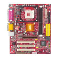
2-17
Hardware Setup
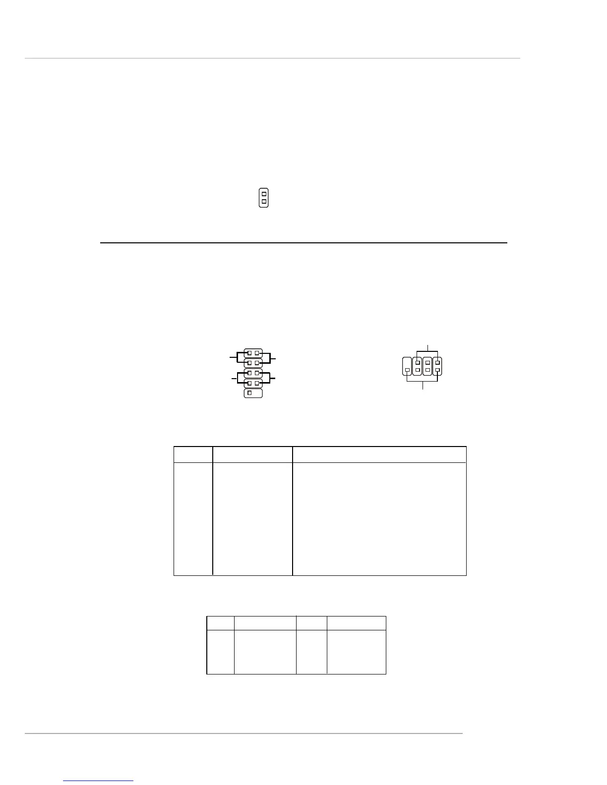
Front Panel Connectors: JFP1 & JFP2
The mainboard provides two front panel connectors for electrical connection
to the front panel switches and LEDs. JFP1 is compliant with Intel
®
Front Panel I/O
Connectivity Design Guide.
PIN SIGNAL DESCRIPTION
1 HD_LED_P Hard disk LED pull-up
2 FP PWR/SLP MSG LED pull-up
3 HD_LED_N Hard disk active LED
4 FP PWR/SLP MSG LED pull-up
5 RST_SW_N Reset Switch low reference pull-down to GND
6 PWR_SW_P Power Switch high reference pull-up
7 RST_SW_P Reset Switch high reference pull-up
8 PWR_SW_N Power Switch low reference pull-down to GND
9 RSVD_DNU Reserved. Do not use.
JFP1 Pin Definition
PIN SIGNAL PIN SIGNAL
1 GND 2 SPK-
3 SLED 4 BUZ+
5 PLED 6 BUZ-
7 NC 8 SPK+
JFP2 Pin Definition
Power LED
Speaker
1
2
7
8
JFP2
JFP1
1
910
Reset
Switch
Power
LED
Power
Switch
2
HDD
LED
Chassis Intrusion Switch Connector: JCI1
This connector is connected to 2-pin connector chassis switch. If the Chassis
is open, the switch will be short. The system will record this status. To clear the
warning, you must enter the BIOS setting and clear the status.
JCI1
 Loading...