40
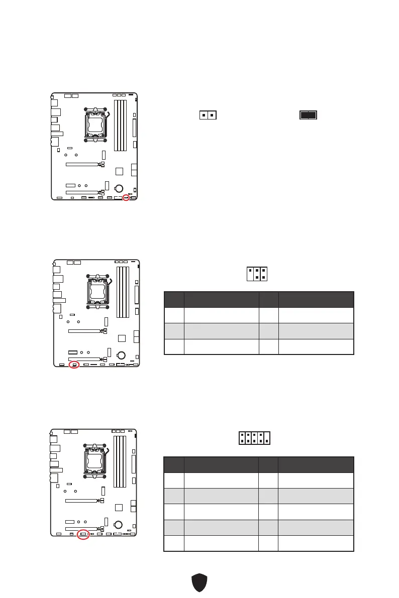
JDASH1 : Tuning Controller connector
This connector is used to connect an optional Tuning Controller module.
Normal
(default)
Boot with the saved
BIOS settings.
Enabled
Apply the BIOS default
settings and lower PCIe
(from CPU) mode for
Safe Boot.
JOCFS1: Safe Boot Jumper
This jumper is used for Safe Boot. Once enabled, the system will boot with default
settings and lower PCIe (from CPU) mode.
Pin Signal Name Pin Signal Name
1 No Pin 2 NC
3
MCU_SMB_SCL_M
4 MCU_SMB_SDA_M
5 VCC5 6 Ground
1
2
5
6
JCOM1 : Serial Port connector
This connector allows you to connect the optional serial port with bracket.
Pin Signal Name Pin Signal Name
1 DCD 2 SIN
3
SOUT
4 DTR
5 Ground 6 DSR
7 RTS 8 CTS
9 RI 10 No pin
1
2 10
9
 Loading...