2-16
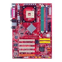
MS-7043 ATX Mainboard
JSP1
1 11
12 2
PIN SIGNAL DESCRIPTION PIN SIGNAL DESCRIPTION
1 VCC5 VCC 5V 2 VDD3 VDD 3.3V
3 SPDFO S/PDIF output 4 (No Pin) Key
5 GND Ground 6 SPDFI S/PDIF input
7 LFE-OUT Audio bass output 8 SOUT-R Audio right surrounding output
9 CET-OUT Audio center output 10 SOUT-L Audio left surrounding output
11 GND Ground 12 GND Ground
JSP1 Pin Definition
S-Bracket (SPDIF) Connector: JSP1 (Optional)
The connector allows you to connect a S-Bracket for Sony & Philips Digital
Interface (SPDIF). The S-Bracket offers 2 SPDIF jacks for digital audio transmission
(one for optical fiber connection and the other for coaxial), and 2 analog Line-Out
jacks for 4-channel audio output.
To attach the fiber-optic cable to optical SPDIF jack, you need to remove the
plug from the jack first. The two SPDIF jacks support SPDIF output only. For more
information on the S-Bracket, refer to Appendix: Using 2-, 4-, or 6-Channel Audio
Function.
Optional S-Bracket
SPDIF jack (optical)
SPDIF jack (coaxial)
Analog Line-Out jack
Connect to JSP1

 Loading...