14
Overview of Components
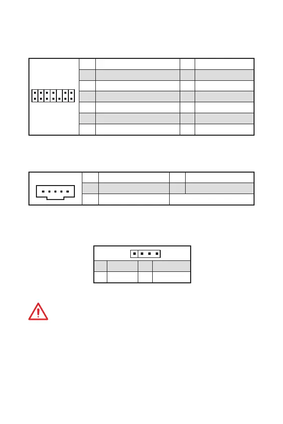
JTPM1: TPM Module Connector
This connector is for TPM (Trusted Platform Module). Please refer to the TPM
security platform manual for more details and usages.
1
2 14
13
1 LPC Clock 2 3V Standby power
3 LPC Reset 4 3.3V Power
5 LPC address & data pin0 6 Serial IRQ
7 LPC address & data pin1 8 5V Power
9 LPC address & data pin2 10 No Pin
11 LPC address & data pin3 12 Ground
13 LPC Frame 14 Ground
JTBT1: Thunderbolt Add-on Card Connector
This connector allows you to connect the add-on Thunderbolt I/O card.
1
1 FORCE_PWR 2 SCI_EVENT
3 SLP_S3# 4 SLP_S5#
5 Ground
Important
y
The JRGB1 connector supports 5050 RGB LED strip (12V/G/R/B) with the maximum
power rating of 3A (12V).
y
Please keeping the LED strip shorter than 2 meters to prevent dimming.
y
Always turn off the power supply and unplug the power cord from the power outlet
before installing or removing the LED strip.
y
Please use MSIs software to control the extended LED strip.
JRGB1: RGB LED connector
The JRGB1 connector allows you to connect the 5050 RGB LED strips 12V.
1
1 +12V 2 G
3 R 4 B
 Loading...