Wheels, non-drive axles and doors
19
Wheels
All of the wheels (drive and non drive) are held on with
a nylock lock nut.
To remove/replace the wheel:
1. Lift and safely support the mower.
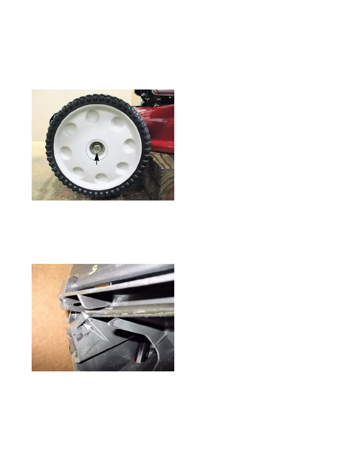
2. Remove the nut with a 1/2” wrench. See Figure 4.1.
3. Slide the wheel off of the axle.
4. Install the wheel by following the previous steps in
reverse order.
NOTE: Apply a small amount of a dry lubricant to the axle
shaft before sliding the wheel on.
NOTE: Apply a small amount of releasable thread locking
compound such as Loctite® 242 (blue) to the lock
nut or replace it with a new one.
NOTE: Tighten the wheel nuts to a torque of 80 - 100 in lbs
(9 - 11 Nm)
5. Test run the mower in a safe area before returning it
to service.
Non-drive axles
All “A” and “B” series mowers have a solid rear axle.
Front axles on all “A” and “B” series mowers that are not
self propelled are also solid. The height adjuster handle is
part of the axle and can not be serviced separately.
To remove/replace the axle:
1. Remove the wheels by following the procedure
described in the previous section of this chapter.
2. Gently spread apart the support arms.
See Figure 4.2.
NOTE: If a support arm breaks, the entire sub-frame must
be replaced.
3. Pull the axle out of the sub-frame.
4. Install the axle by following the previous steps in
reverse order.
5. Test run the mower in a safe area before returning it
to service.
Figure 4.1
Wheel nut
Figure 4.2
Support arms
CHAPTER 4: WHEELS, NON-DRIVE AXLES AND DOORS
 Loading...