R-Series Models RP and RH Temposonics
®
Linear-Position Sensors - SSI Output
Product Data Sheet, Part No.: 550989 Revision E (EN) 05/2014 MTS Sensors8
R-Series Model RH Rod-Style Sensor
Dimension References
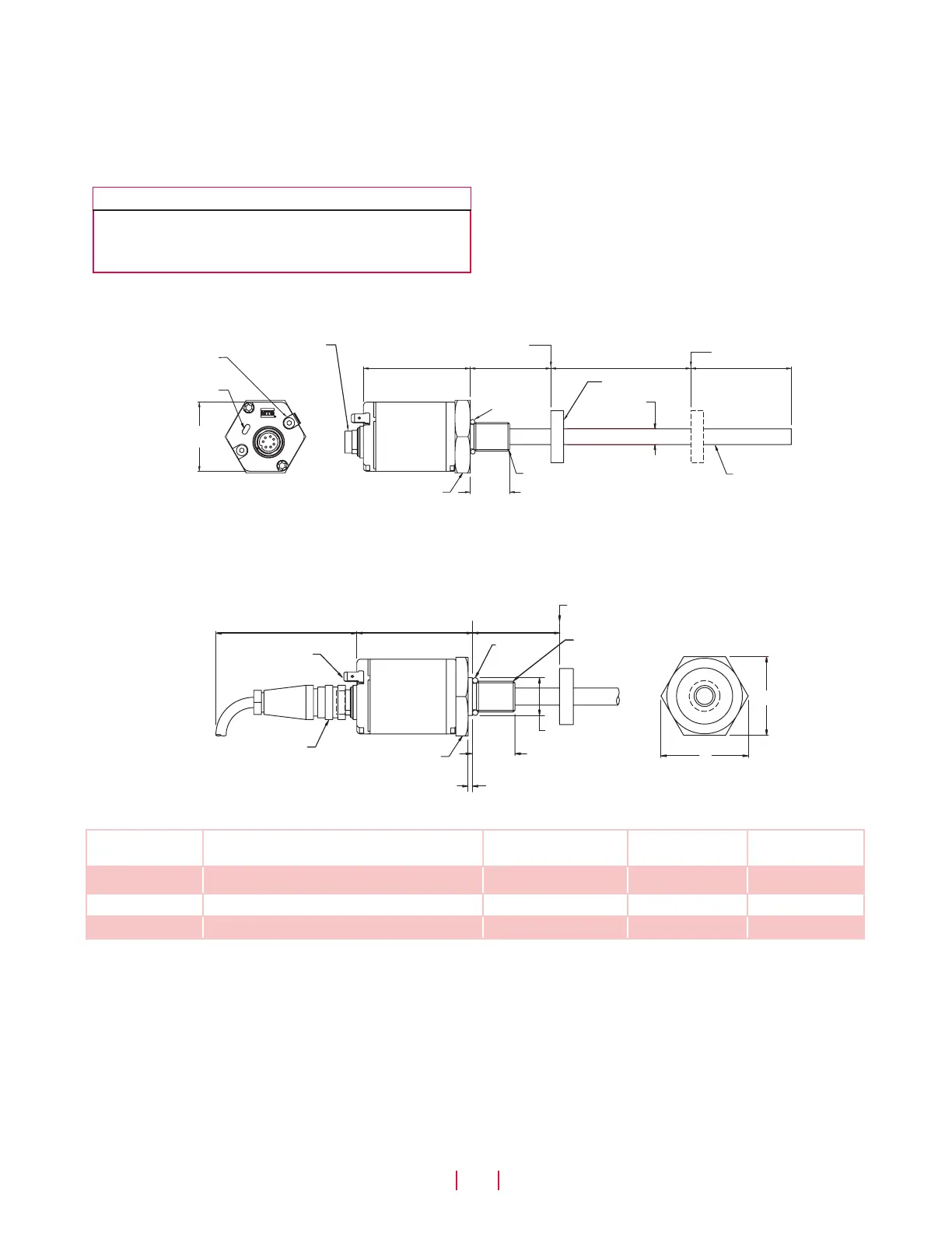
Model RH rod-style sensor dimension references
The Temposonics R-Series rod-style sensor (Model RH) offers modular construction, flexible mounting configurations, and easy installation.
The Model RH sensor is designed for mounting in applications where high pressure conditions exist, (5000 psi continuous, 10,000 psi spike),
such as inside hydraulic cylinders. The Model RH sensor (see Figure 9) may also be mounted externally in many applications.
Stroke-dependent Dead Zones:
Stroke length:
25 mm (1 in.) - 5000 mm (197 in.)
5005 mm (197.1 in.) - 7620 mm (300 in.)
Dead zone:
63.5 mm (2.5 in.)
66 mm (2.6 in.)
MODEL RH, ROD-STYLE SENSOR WITH RING MAGNET (MAGNET ORDERED SEPARATELY)
Drawing is for reference only, contact applications engineering for tolerance specific information.
Figure 11. Model RP Profile-style sensor dimension reference (Shown with D70 Integral connector option)
Diagnostic LEDs
44 mm
(1.7 in.)
68 mm
(2.7 in.)
51 mm
(2 in.)
Male, 7-Pin (D70)
Integral connector
Beginning of stroke ‘Null’ position
End of stroke ‘Span’ position
Electronics
housing
Null zone
Stroke length
Flat-faced Hex
flange type ‘S ’
Sensor rod
10 mm
(0.39 in.) dia.
25 mm
(0.98 in.)
Dead zone
hex screws (2X)
O-Ring
Ring magnet
(refer to note
‘Stroke dependent
dead zones’)
Refer to ‘Table 2’ for
‘(A) Flange threads’
D70
integral connector option
MODEL RH, ROD-STYLE SENSOR WITH 7-PIN MATING CONNECTOR (MAGNET ORDERED SEPARATELY)
Drawing is for reference only, contact applications engineering for tolerance specific information.
Figure 12.
B
68 mm (2.7 in.)
Grounding lug
76 mm (3 in.)
25 mm
(0.98 in.)
2.5 mm (0.1 in.)
25 mm (1 in.)
Beginning of stroke ‘Null’ position
O-Ring
C
Electronics
housing
Refer to‘Table 2’
‘(B) dimensions’ and ‘(C) dimensions’
Refer to ‘Table 2’
‘(A) Flange threads’
Raised-face hex
flange type ‘T ’
Mating connector
7-pin DIN
51 mm (2 in.)
Model RH Rod-style sensor dimension reference (Shown with mating cable connector)
Housing style
flange type Description (A) Flange threads (B) Dimensions (C) Dimensions
T US customary threads with raised-face flange 3/4" - 16 UNF-3A 1.75 in. 2 in.
S US customary threads with flat-faced flange 3/4" - 16 UNF-3A 1.75 in. 2 in.
M Metric threads with flat-faced Flange M18 x 1.5 46 mm 53 mm
Table 2. Model RH Rod-style sensor housing style and flange type references
 Loading...


