EasyManua.ls Logo

Mueller E-Star OESE-A51-HFC User Manual

Mueller E-Star OESE-A51-HFC
48 pages
To Next Page IconTo Next Page
To Previous Page IconTo Previous Page
Page #37 background imageLoading...
Page #37 background image
Mueller E-Star OESE 3.5 and 5 HP HFC Condensing Unit
Installation and Operation Manual, Part No. 8828747 Effective April 13, 2020
15.1 ZB26KCE SINGLE-PHASE, 208/230 V COMPRESSOR DATA CHART
31
Section 15.0 – Compressor Data Charts
Condensing Temperature °F (Sat. Dew Pt. Pressure, psig)
140.0
C
(413)
P
A
M
E
%
C
130.0
P
A
(363)
M
E
%
C
120.0
P
A
(319)
M
E
%
C
110.0
P
A
(279)
M
E
%
C
100.0
P
A
(242)
M
E
%
C
80.0
P
A
(179)
M
E
%
C
70.0
P
A
(153)
M
E
%
C
50.0
P
A
(108)
M
E
%
-10.0(25)
0.0(35) 10.0(46) 15.0(52) 20.0(58) 25.0(65)
30.0(73)
35.0(81) 45.0(98)
60 Hz Operation
Evaporating Temperature °F (Sat. Dew Pt. Pressure, psig)
Rating Conditions
65°F Return Gas
0°F Subcooling
95°F Ambient Air Over
ZB26KCE-PFV
HFC-507
COPELAND SCROLL®
PFV 208/230-1-60
MEDIUM
TEMPERATURE
Blue Area Restrictions: 20°F Max Superheat
C:
Capacity (Btu/hr), P: Power (Watts), A: Current (Amps), M: Mass Flow (lbs/hr), E: EER (Btu/Watt-hr), %: Isentropic Efficiency (%).
Nominal
Performance Values5%) based on 72 hours run-in. Subject to change without notice. Current @ 230 V.
©2016 Emerson Climate Technologies, Inc.
Autogenerated Compressor Performance
Printed 1/11/2016
05-184

Table of Contents

Question and Answer IconNeed help?

Do you have a question about the Mueller E-Star OESE-A51-HFC and is the answer not in the manual?

Mueller E-Star OESE-A51-HFC Specifications

General IconGeneral
BrandMueller
ModelE-Star OESE-A51-HFC
CategoryHeat Pump
LanguageEnglish

Summary

Introduction

General Specifications

Details the custom and specialized components of the E-Star OESE condensing units for maximizing energy efficiency.

Installation

Refrigeration Piping and Evacuation

Guidelines for proper brazing, line set insulation, and system evacuation to 500 microns.

Electrical Connections

Guidance on verifying compatibility, securing connections, and following NEC regulations for electrical setup.

Refrigerant Charging

EPA Refrigerant Regulations

Details EPA requirements for technicians performing refrigerant installation or service, including certification.

Initial Refrigerant Charge

Guidance on triple evacuation to 500 microns and the weigh-in method for startup refrigerant charge.

Weigh-In Refrigerant Charging

Step-by-step procedure for accurately weighing in the refrigerant startup charge into the system.

Final Operating Charge

Procedure for fine-tuning the refrigerant charge for optimal system efficiency, including superheat checks.

Operating Features

Refrigerant Cycle

Explanation of the TEV's role in superheat control and the function of the accumulator heat exchanger.

Expansion Valve

TEV Selection and Installation

Guidance on field adjusting the TEV for optimal superheat and critical aspects of its location and sizing.

Checking and Adjusting Superheat

Procedure for measuring and adjusting evaporator superheat using the TEV.

Electrical Schematics

5 HP, 460/60/3 Wiring Schematic (Effective After September 1, 2007)

Wiring diagram for 5 HP units with 460/60/3 phase, for control cabinets with 24-volt control output.

5 HP, 460/60/3 Wiring Schematic (Effective Until August 31, 2007)

Wiring diagram for 5 HP units (pre-Sept 2007) with 460/60/3 phase and 24-volt control output.

Pressure Switches and Fan Control

Equipment Markings (Continued)

Warning: Disconnect Power Before Screen Guard Removal

Mandates disconnecting power before removing the screen guard to prevent electrical hazards.

Warning: Risk of Electric Shock

Crucial warning about disconnecting all remote power supplies before performing any servicing.

Safety

Safety Alert

General safety warning that improper handling or service can create health hazards.

Technical Data

Compressor Data Charts

ZB26KCE Single-Phase, 208/230 V Compressor Data Chart

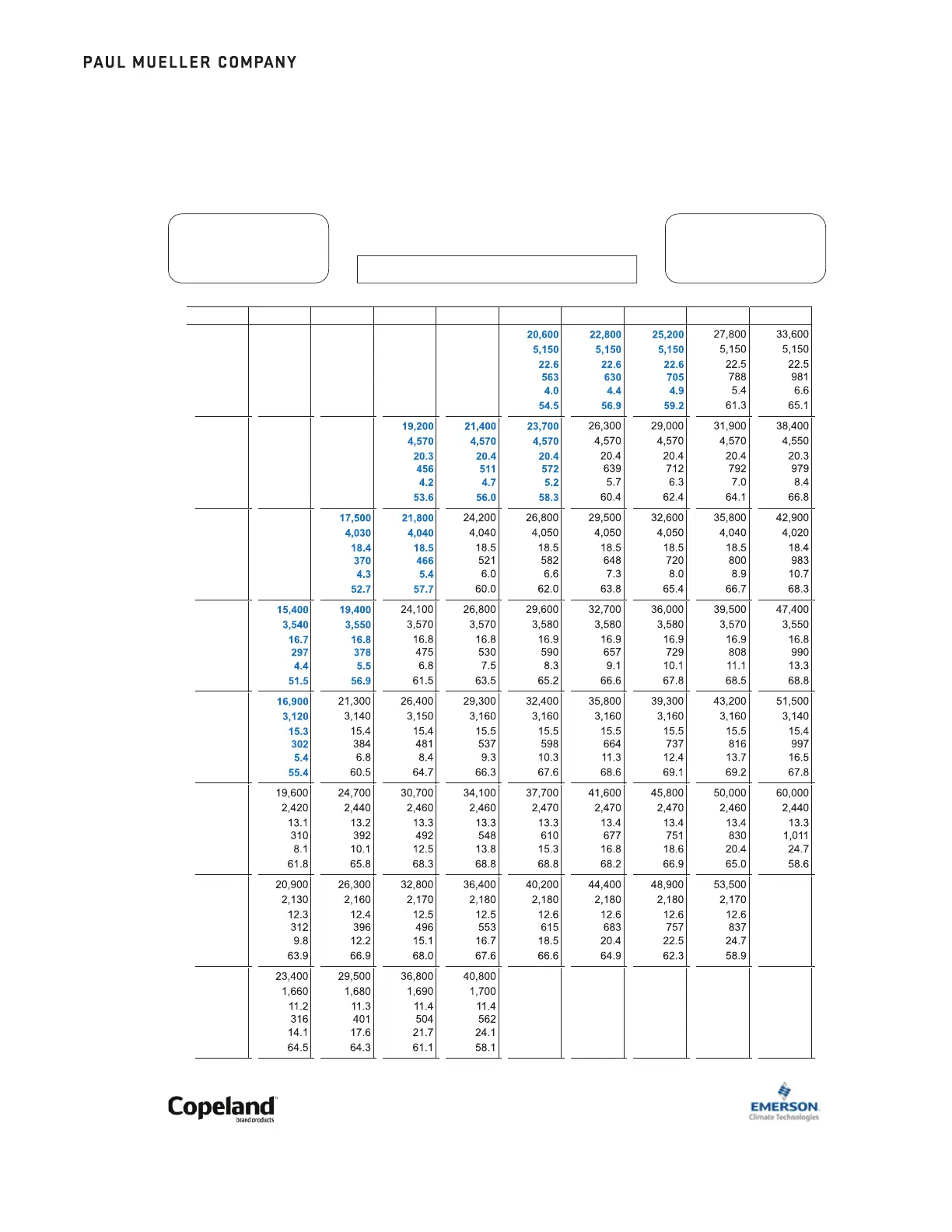
Performance data for ZB26KCE single-phase compressors under various operating conditions.

ZB26KCE Three-Phase, 208/230 V Compressor Data Chart

Performance data for ZB26KCE three-phase compressors under various operating conditions.

ZB38KCE Single-Phase, 208/230 V Compressor Data Chart

Performance data for ZB38KCE single-phase compressors under various operating conditions.

ZB38KCE Three-Phase, 208/230 V Compressor Data Chart

Performance data for ZB38KCE three-phase compressors under various operating conditions.

ZB38KCE Three-Phase, 460 V Compressor Data Chart

Performance data for ZB38KCE three-phase compressors at 460V under various operating conditions.

R-507 Pressure Temperature Chart

Related product manuals