Section 2 Installation
Part Number 000003912 6/17 2-23
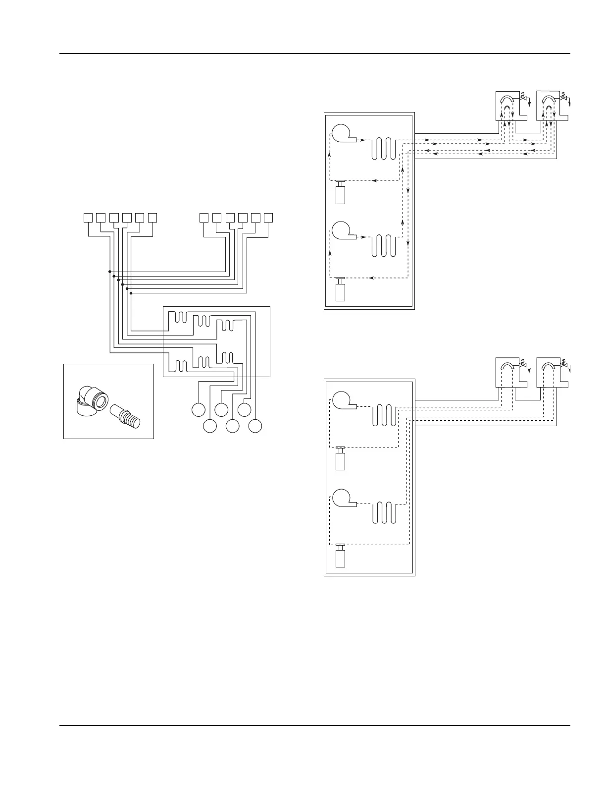
CONNECTING SUPPLY LINES
Pre-installation of towers is required and the appropriate
syrup supply must be connected to the corresponding
tower. The valves are numbered 1-6, 1-8, or 1-10 from
left to right viewing from the front of the tower.
1. For a two (2) tower installation, refer to the Syrup
Supply Line Diagram below. The syrup product
supply boxes can be positioned on a BIB rack in a
convenient location near the soda system.
Syrup Supply Line Diagram (Valve #6 Water Only)
NOTE: Refer to the optional equipment component
installation instructions for completion (if applicable) of
the beverage system. Do not connect the syrup supply
at this time.
2. Locate the conduit supply lines for the refrigeration
unit. There are four (4) 1/2" (1.27 cm) carbonated
water lines marked in sets for the system. Connect
the yellow carbonated water supply line (7) to the
yellow carbonated water return line (A). Connect the
blue carbonated water supply line (8) to the blue
carbonated water return line (B). Refer to the
Carbonated Water Supply Line Diagram below.
Interlaced Tower
Non-interlaced Tower
Dispensing Tower No. 1
“T”
Connections
John Guest to Adapter
Syrup
Supply
Syrup
Coils
Note: Some
equipment may
provide more
product cooling
capability.
6
531
42
Circ.
Pump
Carb.
Tan k
Heat
Exchanger
Circ.
Pump
Carb.
Tan k
Conduit
Conduit Tee
Tower 1
Tower 2
Refrigeration Unit
Heat
Exchanger
Blue
Yell ow
Yellow
Blue
Two Circulation Pumps – Two Circuits
Circ.
Pump
Carb.
Tan k
Heat
Exchanger
Circ.
Pump
Carb.
Tan k
Conduit
Conduit Tee
Tower 1
Tower 2
Refrigeration Unit
Heat
Exchanger
Two Circulation Pumps – Two Circuits
 Loading...