2201Q4JE-MY-C9-N_2018.01.
Chapter 2 Compressor Specifications and Structure
Compound 2-stage Screw Compressor 4032**C 2.5 Mechanisms
2-9
2.5 Mechanisms
2.5.1 Basics of the Screw Compressor
The screw compressor is categorized as a positive displacement rotary compressor.
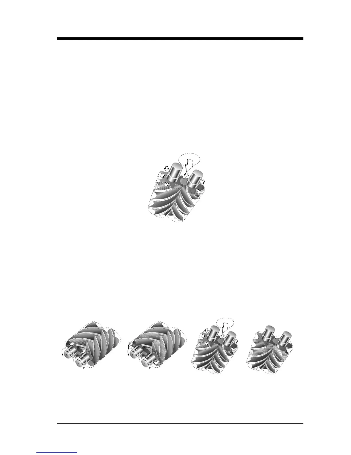
As shown in Figure 2-3, the refrigerant (gas) is continuously compressed by the 3-dimensional spaces
that are formed by a pair of male and female screw rotors (with different sectional profiles) and the
casing, as the spaces change continuously.
The rotor having 4 protruding lobe profiles is called a male rotor or M rotor, and the rotor having 6
concave lobe profiles is called a female rotor or F rotor. In this manual, they are referred to as M rotor
and F rotor.
The compressor is driven by the motor connected to the shaft of the M rotor.
Figure 2-3 Compressor Mechanism
2.5.2 Suction Process
As shown in Figure 2-4, the rotors with different lobe profiles are engaged. As the rotors turn, the
volume between the M and F rotor lobe profiles and the compressor casing gradually increases starting
from the suction side.
As the rotation continues, at a certain point when the volume reaches its maximum, the rotors isolate
the gas (volume), which is enclosed by the rotors and the compressor casing, from the suction port and
then continues rotation.
Figure 2-4 Suction Process

 Loading...

