2201Q4JE-MY-C9-N_2018.01.
Chapter 2 Compressor Specifications and Structure
Compound 2-stage Screw Compressor 4032**C 2.6 Gas and Oil Flow
2-13
2.6 Gas and Oil Flow
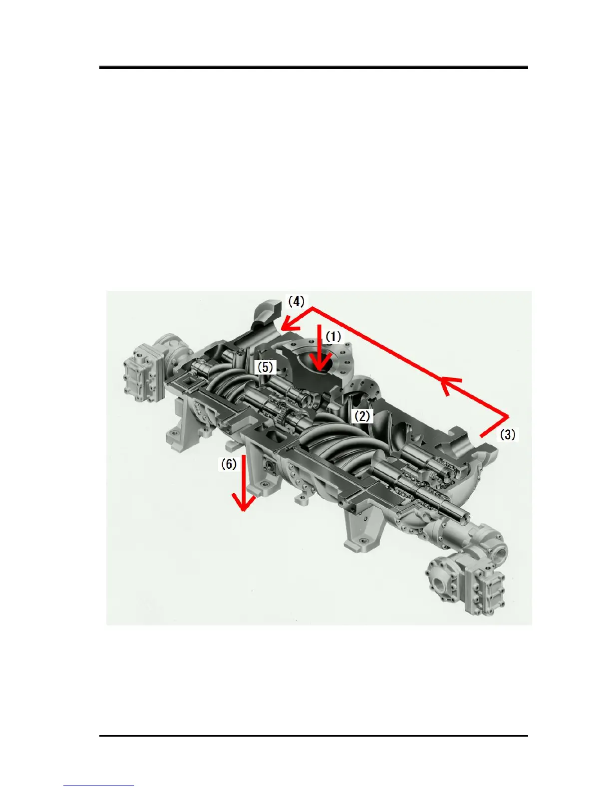
The compression process of the screw compressor is as described in the preceding paragraphs.
Gas of the compound 2-stage screw compressor 4032**C is sent from the evaporator, and passes
through the suction strainer and check valve. It is drawn in from the upper central area (1) of the
compressor, compressed at the low-stage side (2), and then discharged at (3).
(3) and (4) are connected with a pipe. At the mid point of the pipe, that gas is mixed with the gas from
liquid cooler which was used for supercooling.
Gas compressed at the low-stage is, while kept mixed with lubricating oil, suctioned from (4) into the
high-stage.
After being further compressed at (5), the gas with lubricating oil is discharged from (6), and is sent to the
condenser via an oil separator.
Even if without intermediate gas cooling, oil provides cooling effect.
So, the high-stage discharge temperature is maintained at a temperature not higher than 90 °C.
Figure 2-11 Gas Flow

 Loading...

