NAPCO Gemini C-Series Control Panel Installation Instructions--Volume 3
Installation Instructions, Volume 3 Page 17
These instructions are designed to help resolve a ground fault System Trouble on the Gemini C-Series (GEMC) con-
trol panels, for combination Burg/Fire systems that use the GEMC-BM (Burglary Module), GEMC-BM/PS (Burglary
Module with Power Supply) and/or the GEMC-BSLC (Burglary SLC Module). The ground fault occurs when earth
ground is shorted to a wire extending from the control panel. Use the Burglary and/or Fire Ground Fault Troubleshoot-
ing Chart (see next page) and a volt meter with the procedure that follows.
With GEMC Fire-only or combination Fire and Burglary Alarm systems: A Fire alarm system disabled for servic-
ing is no longer protecting the individuals within the premises; therefore extra measures MUST be taken (as required
by the authority having jurisdiction) to protect these individuals before the Fire system is disabled. It is far easier to
disable and service the Burglary portion of the system alone, since the Fire portion can remain in operation. There-
fore, the most rational first step is to always test the Burglary portion of the system before taking the extra measures
required when testing the Fire portion of the system. All tests start with the following preliminary voltage reading:
1. Measure the DC voltage between system ground and earth ground by placing your DC volt meter negative probe
to AUX Power system ground (terminal 23), and the positive probe to earth ground (terminal 1). Make note of the
voltage reading in writing. A "normal" reading without a ground fault is approximately 19V (with a ground fault,
the abnormal voltage reading could be higher or lower than 19V).
With the abnormal voltage reading noted, find this voltage in the first column of the Burglary and/or Fire Ground
Fault Troubleshooting Chart to help find the likely shorted wire. If the abnormal voltage reading appears on both
charts, test the Burglary portion first; if the abnormal voltage reading appears on the Fire chart only, it is still worth
testing and ruling out the Burglary portion of the system before the Fire portion. With the general information you
learned with the charts, the following steps will help you confirm the location of the ground fault wire.
Test the Burglary portion of the system:
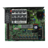
2. Without removing power, place the Burg Service Jumper (located on the bottom left of the motherboard) from
OFF to ON; the red LED to the left of the jumper lights indicating the Burglary/Access Control portion of the sys-
tem is disabled.
3. If the GEMC-BM, GEMC-BM/PS or GEMC-BSLC module(s) are used: The general idea is to unplug each of
these Burglary modules from the system, one by one, to see if (by removing the problem module) the meter read-
ing returns to the "normal" 19V. With the volt meter probes in place (negative probe to terminal 23, positive probe
to terminal 1), unplug one of these Burglary modules from the motherboard and observe the meter voltage read-
ing. If the voltage does NOT return to the normal 19V, the ground fault is NOT due to the wires extending from
that unplugged module (reconnect and try the next module). If the voltage DOES return to the normal 19V, the
ground fault IS likely due to the wires extending from the module that was unplugged.
Confirm your results: With the suspect Burglary Module still unplugged, remove the meter probes and set your
meter to ohms (Ω resistance). Place one probe to earth ground (terminal 1), and place the other probe on each
Burglary Module terminal one at a time and take a reading for each. When the resistance reads low (close to
zero), the shorted wire terminal is likely found. Disconnect the wire(s) from the terminal and test the resistance of
each individual wire(s); the resistance will read low for the shorted wire. Trace the wire and correct the fault to
clear the trouble.
4. If each Burglary Module has been disconnected from the motherboard and the voltage has not yet re-
turned to the normal 19V, the problem is a ground fault on a Fire system wire. Before attempting the follow-
ing steps, take the appropriate measures to protect individuals in the premises, as required by the AHJ.
With the Burg Service Jumper still in the ON position and the red LED (to the left of the jumper) is still lit to indi-
cate the Burglary/Access Control portion of the system is disabled, proceed as follows:
5. Use the same general procedure outlined in step 3, but test each Fire module. With the volt meter probes in
place (negative probe to terminal 23, positive probe to terminal 1), unplug each of the Fire modules one at a time,
each time checking if the earth ground / system voltage has returned to 19V. Continue with the procedure in step
3 until the shorted wire is identified. Trace the wire run until the ground fault is found and remove it.
6. Confirm the earth ground terminal has returned to 19V.
7. Reconnect all wires to their correct terminals and reconnect all Modules. Place the Burg Service Jumper back to
the OFF position to restore Burglary system operation.
Test the system and resume normal premises operation.
GEMC C-SERIES CONTROL PANEL
GROUND FAULT TROUBLESHOOTING INSTRUCTIONS

 Loading...


