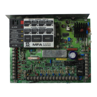
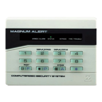
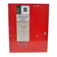
NAPCO Gemini C-Series Control Panel Installation Instructions--Volume 3
Page 4 Installation Instructions, Volume 3
SPECIFICATIONS AND RATINGS
* Must be reduced if an insufficient number of standby batteries are used. Refer to Battery Standby chart.
Note: See individual accessory work instructions (WI's) for exceptions and
other information.
GEMC-255MB, GEMC-128MB, GEMC-96MB and GEMC-
32MB Gemini C-Series Motherboards
Motherboard Power Supply (GEMC-PS24V7A and GEMC-
PS24V4A) Input Power: 120AC 60Hz, 3A; maximum 15A dedicated
branch circuit.
Motherboard (GEMC-255MB, GEMC-128MB, GEMC-96MB and
GEMC-32MB) Input Power: 24VDC, maximum 7A.
Output Power:
Note: All outputs circuits are power-limited.
Note: The GEMC-96MB and GEMC-32MB provide two 2A NAC cir-
cuits (one 24V and one 12V or 24V selectable).
● NAC A, NAC B, NAC C: Regulated 24V NAC circuit; 2A maximum.
When configured for 24V Auxiliary Power, it is a Special Application
output only listed with the GEMC-24VR. The GEMC-24VR output is
Regulated 24VDC, 1A maximum.
● NAC D: When configured for 24V: Regulated 24V NAC circuit;
2A maximum. When configured for 24V Auxiliary Power, it is a Spe-
cial Application output only listed with the GEMC-24VR. The GEMC
-24VR output is Regulated 24VDC, 1A maximum.
● NAC D: When configured for 12V: Regulated 12V NAC circuit,
2A maximum or Regulated 12V Auxiliary Power, 1.4A maximum.
● Fire Aux. Relay Output: Wet: 12V Regulated, 750mA max.; Dry:
Remove shunt for dry contacts; see Wiring Diagram; dry contact
Form C relay rated 30VAC / VDC, 2.5A maximum.
● Two Active low programmable outputs: (2A maximum). Note:
Relies on 2A over-current protection of connected circuit.
● Trouble Sounder Output: 12V Regulated, 30mA.
● E7 and E8 Terminals: Active low open collector outputs; 0.1V, 2A
(wire only to power limited circuits 30VDC or less).
● Auxiliary Power Output: Output 12V Regulated @ 750mA maxi-
mum current.
● Remote Bus Power Output: 12V Regulated @ 750mA maximum
current, supporting up to 7 keypads, zone expansion modules, or
wireless receivers, etc.
● Auxiliary Power 24V Regulated: Can only be supplied through
NAC A, NAC B, NAC C or NAC D (configured for 24V) programmed
for Reverse Polarity and wired to GEMC-24VR. 1.0A* Maximum
(must reduce total combined standby and alarm current by 1.1 times
24V Regulated current).
● Maximum Combined 12V Regulated standby current: Remote
Power + Auxiliary Power + NAC D 12V Output and programmed for
Reverse Polarity + AUX relay if shunt connector is installed:
plus GEMC-BM total standby current plus 25mA;
plus Fire Relay: 35mA (when energized);
plus GEMC-F8ZCPIM total combined standby current +120mA =
1.4A*.
If additional 12V current is required, use the GEMC-12V2APS-
CF (for Fire applications) and/or GEMC-12V2APS-R (for non-
Fire applications) Auxiliary Power supplies.
● Maximum Total Combined 12V Regulated Standby and Alarm
Current: Remote Power + Auxiliary Power + NAC D 12V Output
and programmed for Reverse Polarity + AUX relay if shunt connect-
or is installed + NAC D alarm current:
plus GEMC-BM total combined standby and alarm current + 25mA;
plus GEMC-F8ZCPIM total standby and alarm current).
● Maximum Total Combined 24V Standby: (Total combined 12V
standby plus alarm current times 0.6) + NAC A-D 24V standby cur-
rent:
plus (GEMC-BM total combined standby + 25mA) times 0.6;
plus (GEMC-F8ZCPIM total combined standby + 120mA ) times
0.6;
plus GEMC-BM/PS total combined standby + 25mA;
plus GEMC-FW-SLC total combined 24V standby current;
plus GEMC-BSLC total combined 24V standby current = 1A*.
● Maximum Total combined 24V Standby and Alarm Current:
(Total combined 12V standby plus alarm current times 0.6) + NAC A
-D 24V standby plus alarm current:
plus (GEMC-BM total combined standby and alarm current + 25mA)
times 0.6;
plus GEMC-BM/PS total 24V standby and alarm current + 25mA;
plus GEMC-FW-SLC total combined 24V standby and alarm cur-
rent;
plus GEMC-BSLC total combined 24V standby and alarm current =
6.8A with 7A supply (GEMC-PS24V7A); 3.8A with 4A supply
(GEMC-PS24V4A).
● Maximum Battery Charging Current: Refer to the GEMC-
PS24V7A or GEMC-PS24V4A power supply specifications. The
maximum charging current (trickle charge and fast charge) and the
maximum ampere-hour capacity of the battery that the product is
intended to charge:
Standby Time: See following charts.
Battery Power: See tables in sections "GEMC-PS24V7A 7 AMP
POWER SUPPLY" and "GEMC-PS24V4A 4 AMP POWER SUP-
PLY" (data also located in WI1646 and WI1702).
Loop Voltage: See zone expansion modules.
Loop Current: See zone expansion modules.
Loop Resistance: See zone expansion modules.
Operating Environment: 0-49°C (32-120°F).
Modules that plug into the GEMC-XXXMB
Gemini C-Series Motherboards:
GEMC-BM / PS Burglary Module with Power Supply
Electrical Ratings
Input Power: 24V, 25mA standby from motherboard plus 0.6 multiplied
by the "Total Combined Standby and Alarm Current".
Output Power:
Burg Bell Power: 10.8 - 12.5VDC, 2A maximum.
AUX Power: 11.3 - 12.5VDC, 750mA maximum.
Burg Bus Power ("Remote Bus Power"): 11.2 - 12.5VDC, 750mA
maximum.
PGM1: Active low, 8.2 - 12.0V @ 150mA.
PGM2: Active low, 8.2 - 12.0V @ 150mA.
Aux Relay: Wet 11.2 - 12.5VDC @ 750mA maximum (subtract from
AUX Power); may be set to a dry form "c" relay contact upon removing
or cutting the jumper "R"; output rated 30VAC/DC, 3A (Resistive Load
Only)
Total Combined Standby Current (Auxiliary Power + Burg Bus power
+ Aux Relay power): 750mA.
Total Combined Standby and Alarm Current (Auxiliary power + Burg
Bus power + Aux Relay power + Bell power): 2.5A.
Battery Options:
• One 12V 4AH battery: Maximum standby 500mA + maximum
alarm 1A = total 1.5A.
• One 12V 7AH or 8AH battery: Maximum standby 750mA + maxi-
mum alarm 1.75A = total 2.5A.
Maximum Battery Charging Current: 1A.
Note: Does not affect GEMC-XXXMB standby battery calculations, as
all standby current is from dedicated battery. Maximum GEMC-
XXXMB combined alarm and standby current must be reduced by 0.6
times the combined alarm and standby current of the GEMC-BM/PS
plus 25mA.
GEMC-BM BURGLARY MODULE
Electrical Ratings
Input Power: 12V Regulated, 25mA standby plus total combined
standby and alarm current. Must reduce GEMC-XXXMB total 12V
standby current by GEMC-MB total standby current plus 25mA.
Note: GEMC-BM total standby and alarm current plus GEMC-XXXMB
total 12V standby and 12V alarm current must not exceed 2.5A.

 Loading...


