© National Instruments Corp. 3 FP-TC-120 and cFP-TC-120
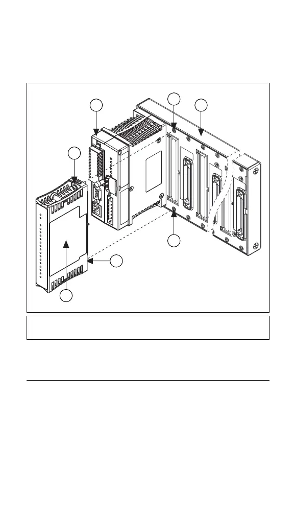
2. Press firmly to seat the cFP-TC-120 on the backplane.
3. Using a number 2 Phillips screwdriver with a shank of at least
64 mm (2.5 in.) length, tighten the captive screws to 1.1 N ⋅ m
(10 lb ⋅ in.) of torque. The nylon coating on the screws prevents
them from loosening.
Figure 2. Installing the cFP-TC-120
Wiring the [c]FP-TC-120
The FP-TB-x terminal bases have connections for each of the eight
differential input channels on the FP-TC-120 and a common
(COM) terminal for connecting a shield to each channel. The
cFP-CB-x connector blocks provide the same connections for the
cFP-TC-120.
Table 1 lists the terminal assignments for the signals associated
with each channel. The terminal assignments are the same for the
FP-TB-x terminal bases and the cFP-CB-x connector blocks.
1 cFP Backplane
2 cFP Controller Module
3cFP-TC-120
4 Captive Screws
5 Screw Holes
4
4
3
2 1
5
5
 Loading...