© National Instruments Corp. 5 FP-TC-120 and cFP-TC-120
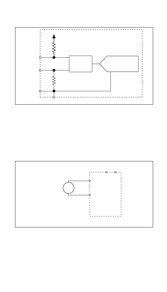
converter (ADC). Figure 3 shows the input circuitry on one
channel.
Figure 3. [c]FP-TC-120 Analog Input Circuitry on One Channel
Connecting Voltage Input Signals
Connect the positive lead of a millivolt signal to the IN(+) terminal
and the negative lead to the IN(–) terminal. If you are using
shielded wiring, connect one end of the shield to the COM
terminal. Figure 4 shows a millivolt source connected to one
channel of the [c]FP-TC-120.
Figure 4. Connecting a Millivolt Source to the [c]FP-TC-120
The input ranges for the voltage inputs are ±25, ±50, ±100, and
–20 to 80 mV. An input signal outside the selected input range
causes the [c]FP-TC-120 to report an
Out of range error for the
affected channel. The [c]FP-TC-120 ignores any configuration of
thermocouple type when you select one of these ranges.
IN(+)
IN(–)
COM
C
+0.7 V
10 MΩ
10 MΩ
Filter
16-Bit
Isolated ADC
[c]FP-TC-120
Millivolt
Source
[c]FP-TC-120
IN(–)
IN(+)
CV
+
–
 Loading...