Chapter 3 Signal Connections
© National Instruments Corporation 3-3 NI 660x User Manual
In addition to these hard-wired filter clocks, you can use any PFI, RTSI, or
internal signal as the source for the filter clock timebase. Use signals with
a duty cycle as close to 50 percent as possible.
If the period of the filter clock timebase is t
fltrclk
, this filter guarantees to
pass pulse widths that are 2*t
fltrclk
or longer and to block pulse widths that
are t
fltrclk
or shorter. A pulse with a width between these two ranges may or
may not pass, depending on the phase of the pulse with respect to the filter
clock timebase.
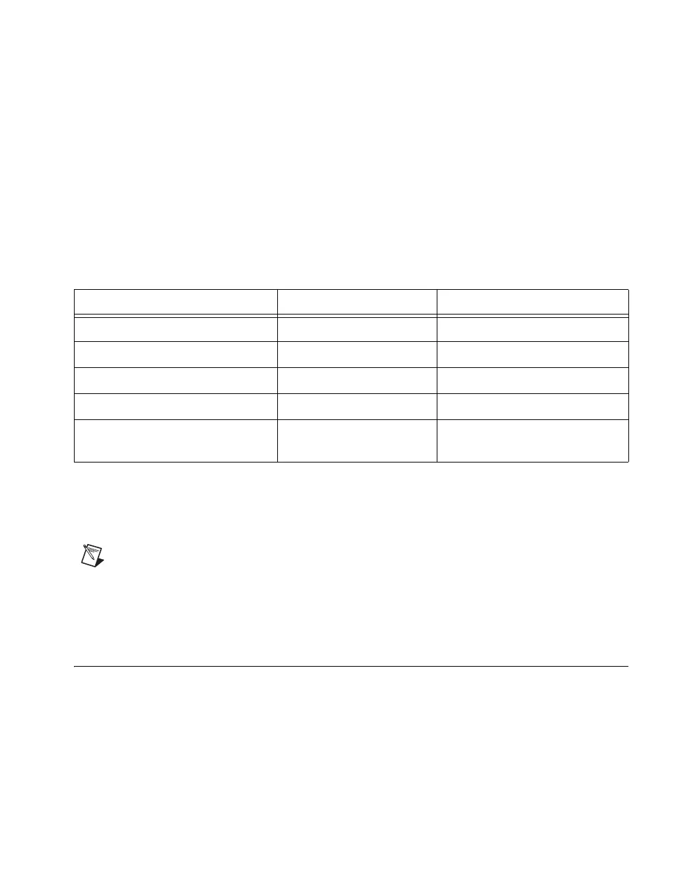
Table 3-1 summarizes the properties of the different filter settings.
You individually configure the filter setting for each PFI line. The filters are
useful to maintain signal integrity. They can prevent measurement errors
caused by noise, crosstalk, or transmission line effects.
Note The digital filters on the NI 660x devices are not enabled by default.
For more information about using the digital filters on your device, refer to
Digital Filtering for Counters in the NI-DAQmx Help.
Power-On State
The PFI lines are weakly pulled down within the NI-TIO ASIC, and the
RTSI lines are weakly pulled high. Connections for pulling up the PFI lines
or for stronger pull-down connections must be made external to the
NI 660x. These connections affect the drive strength of the NI 660x when
the lines pulled up or down are used as outputs.
Table 3-1. Filter Settings
Filter Setting Pulse Width Passed Pulse Width Blocked
5 μs 5 μs 2.5 μs
1 μs 1 μs 500 ns
500 ns 500 ns 250 ns
100 ns 100 ns 50 ns
Programmable setting
with period of clock = t
fltrclk
2*t
fltrclk
t
fltrclk
 Loading...