Chapter 3 Signal Connections
NI 660x User Manual 3-12 ni.com
Counter Source to Counter Out Delay
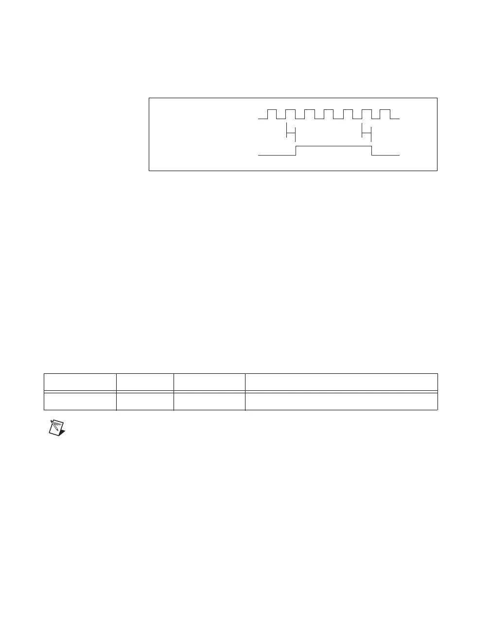
Figure 3-4 shows the CtrnSource to CtrnInternalOutput delay.
Figure 3-4. CtrnSource to CtrnInternalOutput Delay
Figure 3-4 shows the delay between the active edge of the CtrnSource
signal and the active edge of the CtrnInternalOutput signal. In the figure,
the CtrnSource and CtrnInternalOutput signals are active high. If you use
the pulse output mode for the CtrnInternalOutput signal, you will see the
TC pulse one CtrnSource period before the CtrnInternalOutput toggles
under the toggle output mode.
The output delay listed in Table 3-5 is for internal signals. The
corresponding delay values at a connector block are larger due to cable
delays. The TIO device’s isolation circuitry delays the signals further.
For more information about these signal delays, refer to the
NI 660x Specifications document, available for download at
ni.com/manuals.
Note When using duplicate count prevention mode, the minimum period of signal used as
the source of the counter must be greater than or equal to four times the period of the
maximum timebase. For more information, refer to the Duplicate Count Prevention section
of this document.
Table 3-5. Output Delay for Internal Signals
Parameter Typical Maximum Description
Tso 16 ns 26 ns CtrnSource to CtrnInternalOutput delay
CtrnInternalOutput
Tso Tso
CtrnSource
 Loading...