Chapter 3 Signal Connections
© National Instruments Corporation 3-13 NI 660x User Manual
Counter n Gate Signal
You can select any PFI or RTSI, as well as many other internal signals like
the Counter n Gate (CtrnGate) signal. The CtrnGate signal is configured in
edge-detection or level-detection mode depending on the application
performed by the counter. The gate signal can perform many different
operations including starting and stopping the counter, generating
interrupts, and saving the counter contents.
You can export the CtrnGate signal to the I/O connector’s default PFI input
for each CtrnGate. For example, you can export the gate signal connected
to counter 0 to the PFI 38/CTR 0 GATE pin, even if another PFI is inputting
the Ctr0Gate signal. This output is set to high-impedance at startup.
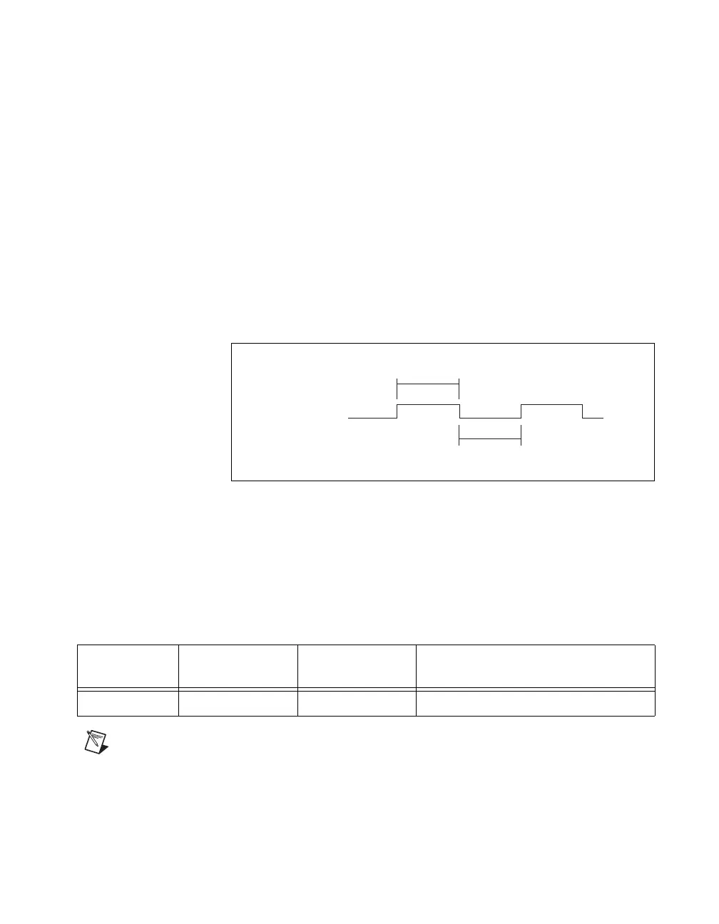
Figure 3-5 shows the timing requirements for the CtrnGate signal.
Figure 3-5. Timing Requirements for CtrnGate Signal
The minimum pulse width and period listed in Table 3-6 is the minimum
required for the internal signals. The TIO device has signal requirements in
order to pass through the isolation circuitry. For more information about
these signal requirements, refer to the NI 660x Specifications document,
available for download from
ni.com/manuals.
Note For buffered measurements, the minimum period required for the CtrnGate signal is
determined by how fast the system can transfer data from your device to computer memory.
Table 3-6. Minimum Pulse Width for CtrnGate Internal Signals
Parameter Minimum
Minimum with
RTSI Connector
Description
Tgatepw 5 ns 5 ns CtrnGate minimum pulse width
CtrnGate
Tgatepw
Tgatepw
 Loading...