7-10 | ni.com
Chapter 7 Counters
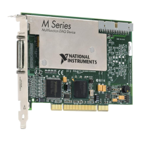
Figure 7-12 illustrates this method. Another option is to measure the width of a known period
instead of a known pulse.
Figure 7-12. High Frequency with Two Counters
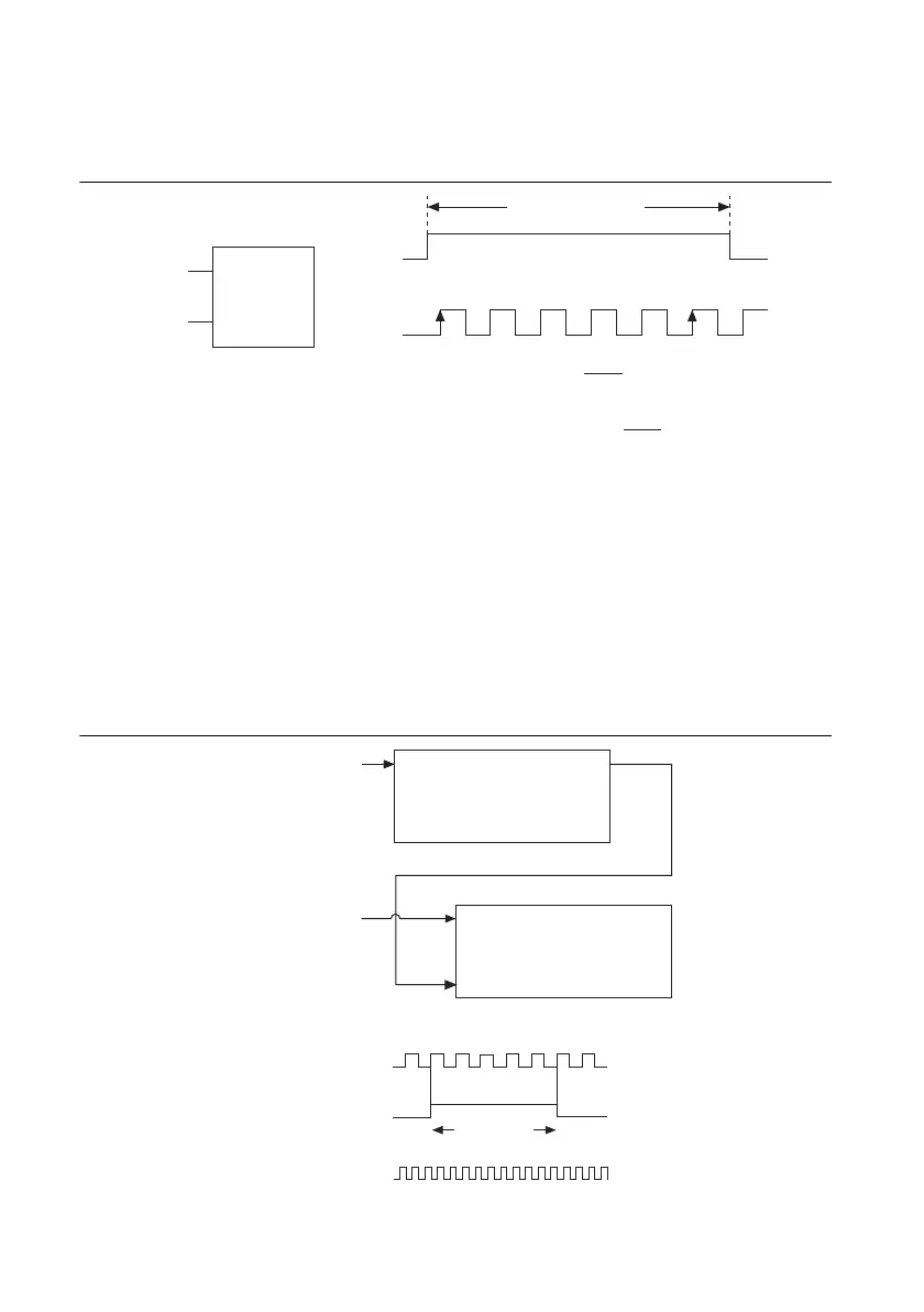
Large Range of Frequencies with Two Counters
By using two counters, you can accurately measure a signal that might be high or low frequency.
This technique is called reciprocal frequency measurement. In this method, you generate a long
pulse using the signal to measure. You then measure the long pulse with a known timebase. The
M Series device can measure this long pulse more accurately than the faster input signal.
You can route the signal to measure to the Source input of Counter 0, as shown in Figure 7-13.
Assume this signal to measure has frequency F1. Configure Counter 0 to generate a single pulse
that is the width of N periods of the source input signal.
Figure 7-13. Large Range of Frequencies with Two Counters
Pulse
F1
Pulse
F1
Gate
Source
12…
N
Pulse-Width
Measurement
T =
N
F1
Frequency of F1 =
T
Width of
Pulse
N
Width of Pulse (T)
SOURCE OUT
COUNTER 0
SOURCE
GATE
OUT
COUNTER 1
Signal to
Measure (F1)
Signal of Known
Frequency (F2)
CTR_0_SOURCE
(Signal to Measure)
CTR_0_OUT
(CTR_1_GATE)
CTR_1_SOURCE
Interval
to Measure
0123 … N
 Loading...
