© National Instruments | 7-33
M Series User Manual
Example Application That Works Correctly (No Duplicate
Counting)
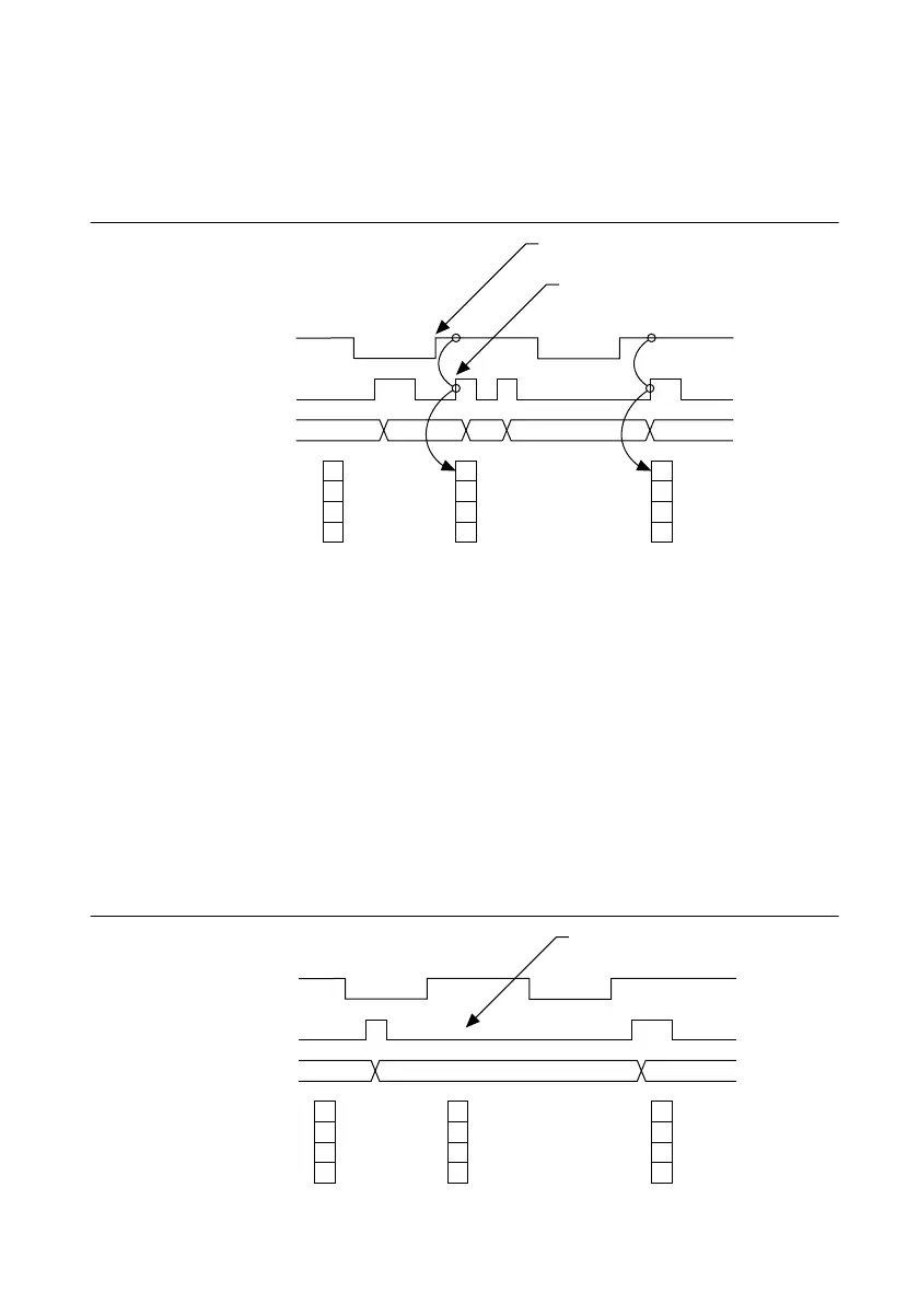
Figure 7-32 shows an external buffered signal as the period measurement Source.
Figure 7-32. Duplicate Count Prevention Example
On the first rising edge of the Gate, the current count of 7 is stored. On the next rising edge of
the Gate, the counter stores a 2 since two Source pulses occurred after the previous rising edge
of Gate.
The counter synchronizes or samples the Gate signal with the Source signal, so the counter does
not detect a rising edge in the Gate until the next Source pulse. In this example, the counter stores
the values in the buffer on the first rising Source edge after the rising edge of Gate. The details
of when exactly the counter synchronizes the Gate signal vary depending on the synchronization
mode. Synchronization modes are described in the
Synchronization Modes section.
Example Application That Works Incorrectly (Duplicate Counting)
In Figure 7-33, after the first rising edge of Gate, no Source pulses occur, so the counter does not
write the correct data to the buffer.
Figure 7-33. Duplicate Count Example
2
7
7
67 12 1
Rising Edge
of Gate
Counter detects rising
edge of Gate on the next
rising edge of Source.
Source
Gate
Buffer
Counter Value
7
67 1
No Source edge, so no
value written to buffer.
Source
Gate
Buffer
Counter Value

 Loading...
