© National Instruments | 7-29
M Series User Manual
You can use these defaults or select other sources and destinations for the counter/timer signals
in NI-DAQmx. Refer to Connecting Counter Signals in the NI-DAQmx Help or the
LabVIEW Help for more information about how to connect your signals for common counter
measurements and generations. M Series default PFI lines for counter functions are listed in
Physical Channels in the NI-DAQmx Help or the LabVIEW Help.
Counter Triggering
Counters support three different triggering actions:
• Arm Start Trigger—To begin any counter input or output function, you must first enable,
or arm, the counter. Software can arm a counter or configure counters to be armed on a
hardware signal. Software calls this hardware signal the Arm Start Trigger. Internally,
software routes the Arm Start Trigger to the Counter n HW Arm input of the counter.
ArmStart.DigEdge.Edge is not supported on M Series devices and modules.
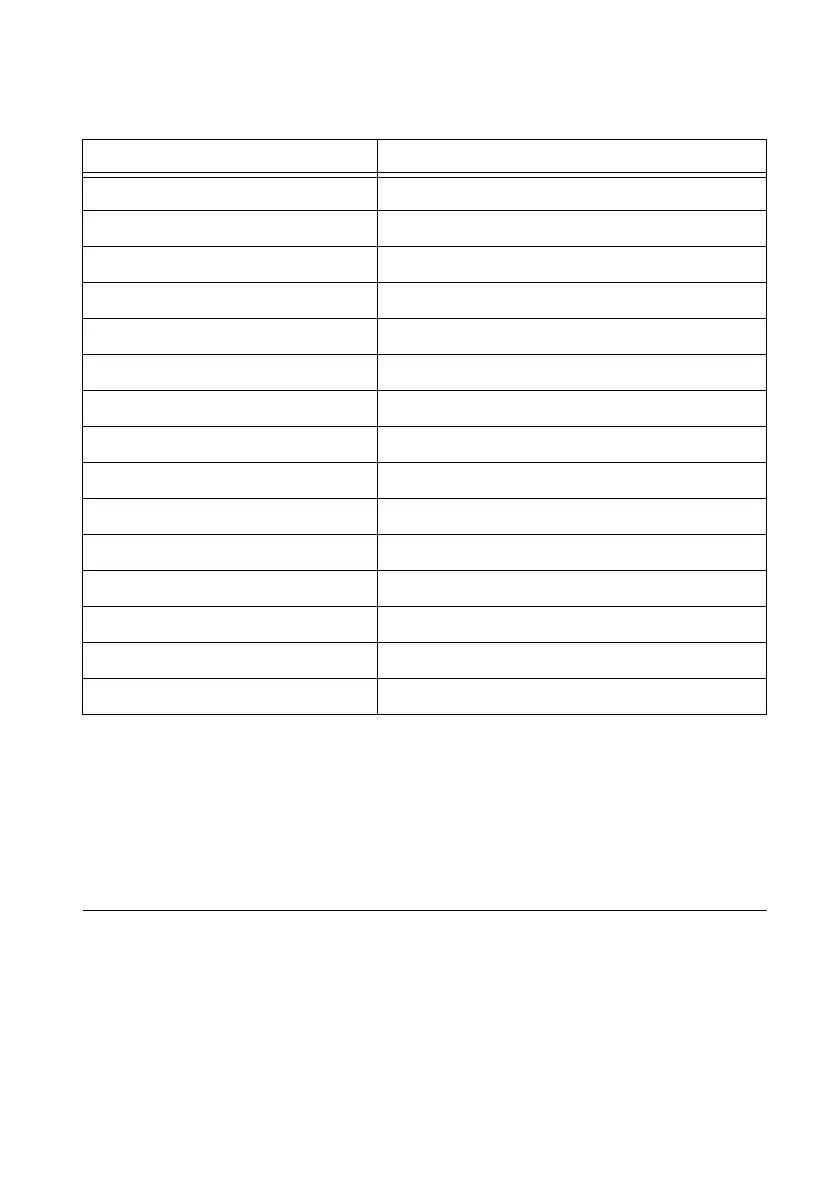
Table 7-6. 68-Pin Device Default NI-DAQmx Counter/Timer Pins
Counter/Timer Signal Default Connector 0 Pin Number (Name)
CTR 0 SRC 37 (PFI 8)
CTR 0 GATE 3 (PFI 9)
CTR 0 AUX 45 (PFI 10)
CTR 0 OUT 2 (PFI 12)
CTR 0 A 37 (PFI 8)
CTR 0 Z 3 (PFI 9)
CTR 0 B 45 (PFI 10)
CTR 1 SRC 42 (PFI 3)
CTR 1 GATE 41 (PFI 4)
CTR 1 AUX 46 (PFI 11)
CTR 1 OUT 40 (PFI 13)
CTR 1 A 42 (PFI 3)
CTR 1 Z 41 (PFI 4)
CTR 1 B 46 (PFI 11)
FREQ OUT 1 (PFI 14)
 Loading...
