EasyManua.ls Logo

National Instruments USB-6003 User Manual

National Instruments USB-6003
37 pages
To Next Page IconTo Next Page
To Previous Page IconTo Previous Page
Page #19 background image
NI USB-6001/6002/6003 User Guide | © National Instruments | 19
The main blocks of the AO circuitry are as follows:
Protection—The protection circuit prevents damage of the buffers in case of a short circuit
or an overvoltage condition.
Buffer—The buffer amplifies the analog signal to the ±10 V range and ensures the driving
capability for the external load.
DAC 0 and DAC 1The Digital to Analog Converters (DAC) convert the digital signals
into low-level analog signals.
AO FIFO—The AO FIFO (first-in-first out) ensures that data is transferred to the DACs
in a timely manner without being affected by USB latencies.
DAC Control—The DAC control sets the DAC data rate and the startup condition, which
could be triggered by PFI 0 or PFI 1.
Connecting Analog Output Signals
The analog output signals are referenced to AO GND. Connect the loads between AO 0 or AO 1
and AO GND.
Figure 12. Connecting the Analog Ouput Loads
Power-On State
The AO exhibits a short glitch when the device is powered on and when the NI DAQ dev ice
exits suspend mode. After power-up, the AO is reset to 0 V.
AO Range
The AO range is ± 10 V.

Other manuals for National Instruments USB-6003

Question and Answer IconNeed help?

Do you have a question about the National Instruments USB-6003 and is the answer not in the manual?

National Instruments USB-6003 Specifications

General IconGeneral
Product NameUSB-6003
ManufacturerNational Instruments
CategoryI/O Systems
InterfaceUSB
Analog Input Channels8 SE/4 DIFF
Analog Input Resolution16 bits
Analog Input Sample Rate10 kS/s
Analog Output Channels2
Analog Output Resolution12 bits
Analog Output Rate150 S/s
Digital I/O Channels12
Counter/Timers1
Power RequirementsUSB Bus Powered
Storage Temperature Range-20 °C to 70 °C
Input Range+/- 10 V
Analog Output Range0 to 5 V
Operating Temperature Range0 °C to 45 °C
Relative Humidity Range10% to 90% (non-condensing)

Summary

Safety Guidelines

Electromagnetic Compatibility Guidelines

Setting Up the NI USB-6001/6002/6003

Installing the Software

Instructions for installing the NI-DAQmx software and related applications.

Preparing the Hardware

Steps to connect the device hardware, including terminal plugs and USB cable.

Verifying the Installation

Using the NI USB-6001/6002/6003 in an Application

Guidance on integrating the device into custom applications.

Example Programs

Information on accessing and utilizing provided software examples for development.

NI-DAQ Assistant

Pinout and Signal Descriptions

Analog Input

Analog Input Modes

Taking Differential Measurements

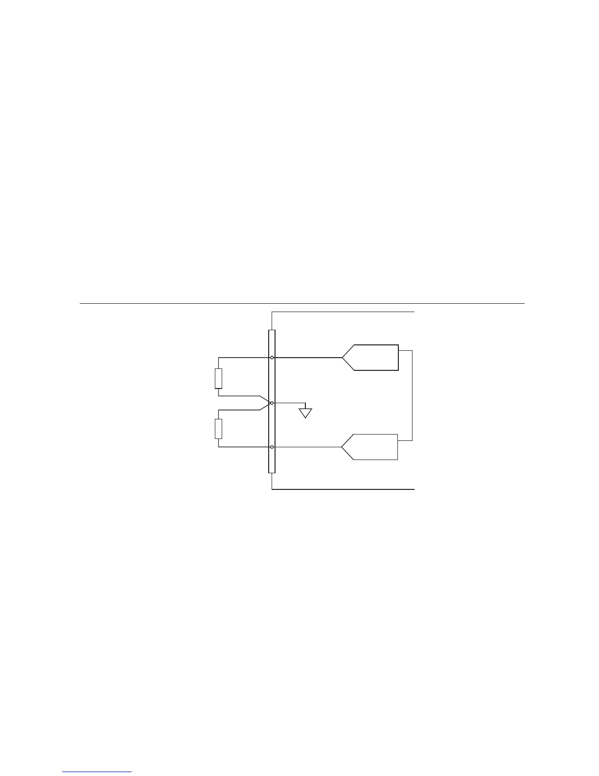
Instructions for connecting and performing differential measurements on analog input channels.

Taking Referenced Single-Ended Measurements

Signal Sources and Recommended Input Configuration

Floating Signal Sources

When to Use Differential Connections with Floating Signal Sources

Guidelines for using differential mode with floating signal sources for optimal accuracy.

When to Use Referenced Single-Ended (RSE) Connections with Floating Signal Sources

Conditions for using RSE mode with floating signal sources.

Ground-Referenced Signal Sources

When to Use Differential Connections with Ground-Referenced Signal Sources

Guidelines for using differential mode with ground-referenced sources.

When to Use Referenced Single-Ended (RSE) Connections with Ground-Referenced Signal Sources

Recommendation against RSE mode for ground-referenced sources.

Input Range

Multichannel Scanning Considerations

Analog Output

Connecting Analog Output Signals

Instructions for connecting loads to the analog output channels.

Digital I/O

PFI 0 and PFI 1

+5 V Power Source

NI-DAQmx

SPECIFICATIONS NI USB-6002

Analog Input

Technical specifications for the analog input channels.

Analog Output

Technical specifications for the analog output channels.

Digital I/O

Technical specifications for the digital input/output functionality.

Device Pinout

Related product manuals