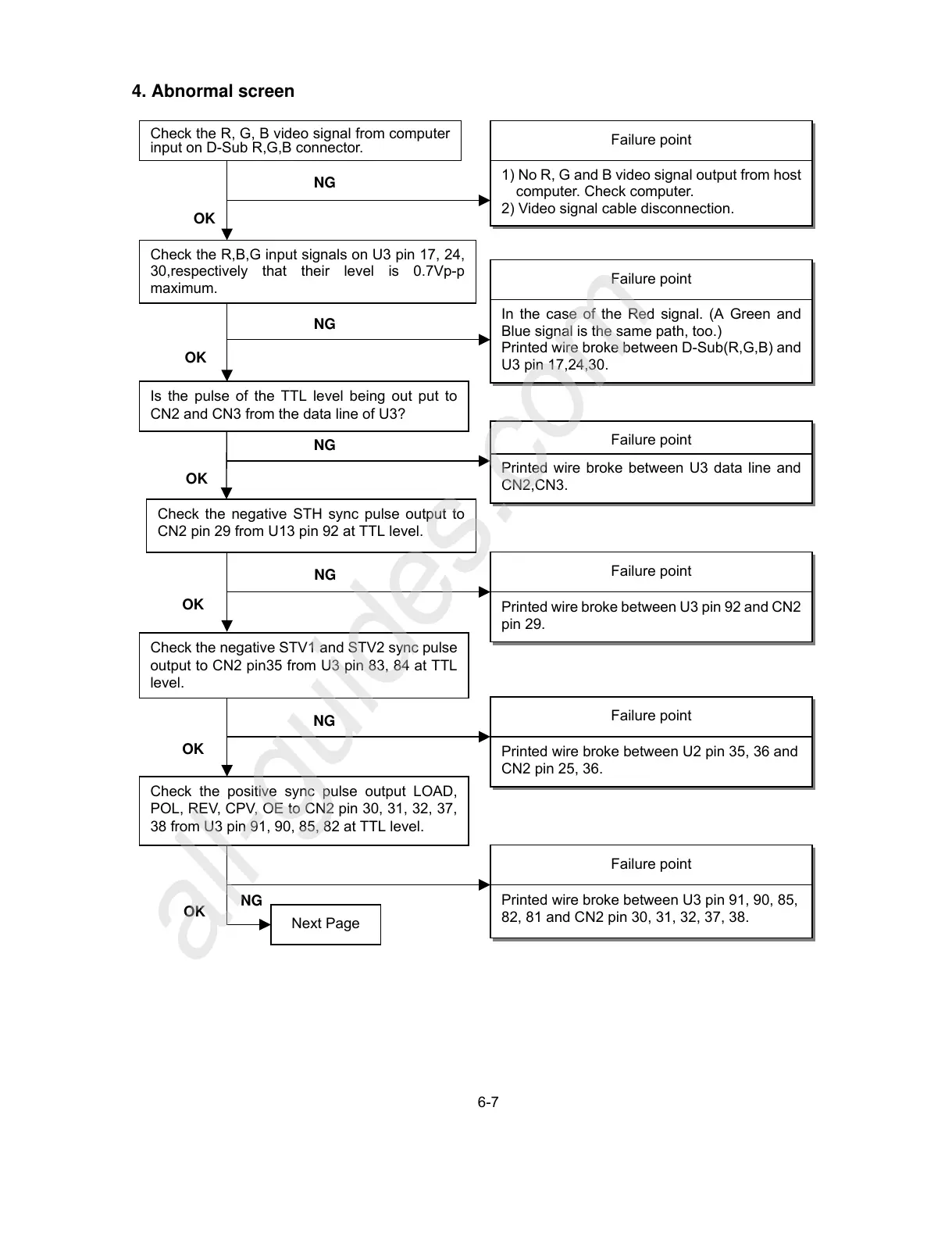
computer. Check computer.
2) Video signal cable disconnection.
Check the R,B,G input signals on U3 pin 17, 24,
30,respectively that their level is 0.7Vp-p
maximum.
Failure point
In the case of the Red signal. (A Green and
Blue signal is the same path, too.)
Printed wire broke between D-Sub(R,G,B) and
U3 pin 17,24,30.
Next Page
OK
Check the negative STH sync pulse output to
CN2 pin 29 from U13 pin 92 at TTL level.
Failure point
Printed wire broke between U3 pin 92 and CN2
pin 29.
NG
OK
Check the negative STV1 and STV2 sync pulse
output to CN2 pin35 from U3 pin 83, 84 at TTL
level.
Failure point
Printed wire broke between U2 pin 35, 36 and
CN2 pin 25, 36.
NG
OK
Failure point
Printed wire broke between U3 pin 91, 90, 85,
82, 81 and CN2 pin 30, 31, 32, 37, 38.
NG
Is the pulse of the TTL level being out put to
CN2 and CN3 from the data line of U3?
NG
Failure point
Printed wire broke between U3 data line and
CN2,CN3.
OK
OK
Check the positive sync pulse output LOAD,
POL, REV, CPV, OE to CN2 pin 30, 31, 32, 37,
38 from U3 pin 91, 90, 85, 82 at TTL level.
 Loading...