N E T A F I M T E C H L I N E
®
C V D E S I G N G U I D E
N E T A F I M T E C H L I N E
®
C V D E S I G N G U I D E
BASIC
DESIGN
STEPS
(continued)
IF AN AUTOMATIC LINE
FLUSHING VALVE IS
NOT DESIRED:
• It is because holding the
water in the Techline CV is
desired and,
• Procedures have been
established to manually
flush the lines during the
season.
• In this case, Techline
Shut-Off Valves
(TLSOV) or
Figure 8 Line Ends (TLFIG8)
should be located along the
exhaust header, or at the
midpoint of a LITE layout.
Techline CV Manual Line
Flush Valve
Techline Shut-Off
Valve #TLSOV
(blank tubing may be
attached to outlet)
Techline CV Lateral
(or Exhaust Header
Valve Box
(Install Per Specs)
Brick Supports
(Three)
3/4" Gravel Sump
(1 Cubic Foot)
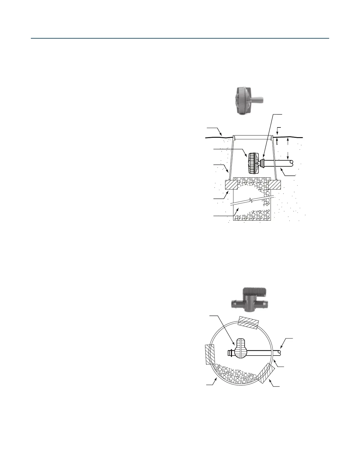
Netafim Line Flushing Valve
IF AN AUTOMATIC
LINE FLUSHING VALVE IS
DESIRED:
• It is because the desire to have
a cleansing action outweighs the
desire to hold the water inside
the tubing when the zone is off.
• As such, place a Line Flushing
Valve (one per each 15 GPM
of zone flow) as far away from
the source as possible. This will
typically be somewhere along
the exhaust header in a GRID
layout and at the midpoint of the
tubing in a LITE layout.
• When Center Feed layouts are
used, install at least one Line
Flushing Valve on each exhaust
header.
• Line Flushing Valves should
be buried in a valve box with a
gravel sump adequate to drain
approximately one gallon of
water.
• See Air/Vacuum Relief Valves on
page 13.
Compression Ring
(Provided)
1"
See Specs
Techline
17mm Tubin
Finish Grade
Valve Box
(see specs)
Brick Supports (3)
3/4" Gravel Sump
(1 cubic foot)
Line Flushing
Valve (TLFV-1)
 Loading...