Hardware Installation
21
NETGEAR Managed Switch
• If the POST fails, the Power LED blinks yellow.
Note: If the PD LED on the front panel of the M4100-D12G and
M4100-D12G-POE+ blinks green, port 1 is connected to a
IEEE802.3af PoE device. Check the PoE device specification to
make sure that it supports IEEE802.3at.
If the Power LED does not light up, check that the power cable is plugged in correctly and
that the power source is good. For more information, see Troubleshooting on page 24.
SFP Modules
SFP modules (sold separately) can be inserted directly into the switch’s ports.
Note: Use only optical transceiver modules that are UL approved and that
are certified as Laser class 1 products.
• AGM731F: SFP module with LC connector
, compatible with the IEEE 802.3z
1000Base-SX standard
• AGM732F: SFP module with LC connector
, compatible with the IEEE 802.3z
1000Base-LX standard
• AFM735: SFP module with LC connector
, compatible with the IEEE 802.3u 100Base-FX
standard
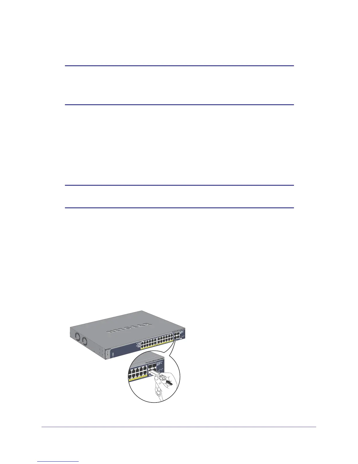
To insert an SFP module into the switch port:
1. Insert the module into the switch port.
2. Press firmly to ensure that the module seats into the connector
.
 Loading...