Install the sensor in a neutral position where the set
temperature is required. A suitable location is on a free
inner wall in a hall approx. 1.5 m above the floor. It is
important that the sensor is not obstructed from meas-
uring the correct room temperature by being located,
for example, in a recess, between shelves, behind a
curtain, above or close to a heat source, in a draft from
an external door or in direct sunlight. Closed radiator
thermostats can also cause problems.
The heat pump operates without the sensor, but if one
wishes to read off the accommodation's indoor temper-
ature in F1245's display, the sensor must be installed.
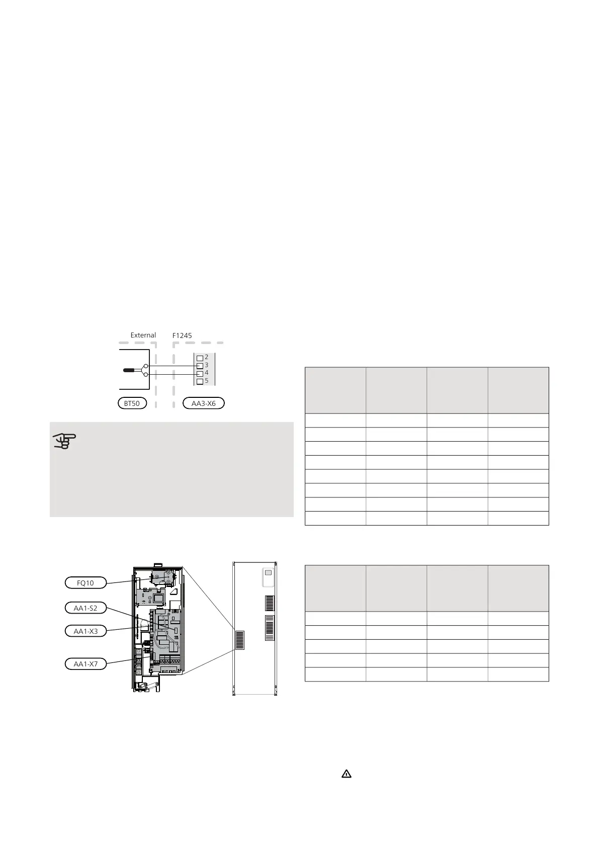
Connect the room sensor to X6:3 and X6:4 on the input
board (AA3).
If the sensor is to be used to change the room temper-
ature in °C and/or to fine-tune the room temperature,
the sensor must be activated in menu 1.9.4.
If the room sensor is used in a room with underfloor
heating, it should only have an indicatory function, not
control of the room temperature.
Caution
Changes of temperature in accommodation
take time. For example, short time periods in
combination with underfloor heating will not
give a noticeable difference in room temperat-
ure.
Settings
ELECTRICAL ADDITION - MAXIMUM OUTPUT
Number of steps, maximum electrical output and supply
on connection for the immersion heater varies depend-
ing on model. See tables.
The electric additional heat may be restricted depending
on the selected country.
On delivery, the immersion heater is connected for a
maximum of 7 kW (switchable to 9 kW).
The immersion heater's output is split into seven steps
(four steps if the immersion heater is switched to max-
imum 9 kW), according to the table below.
Setting max electrical output
Setting maximum output in the electric additional heat
is done in menu 5.1.12.
The table displays the total phase current for the immer-
sion heater at start up. If an immersion heater has
already been started and is not used for its full capacity
the values in the table can be changed because the
control initially uses this immersion heater.
Switching to maximum electrical output
If more than the maximum output (7 kW) for the immer-
sion heater connected on delivery is needed, the heat
pump can be switched to maximum 9 kW.
Move the white cable from terminal block X7:23 to ter-
minal block X3:13 (the seal on the terminal block must
be broken) on the immersion heater card (AA1).
3x400V V (maximum electrical output, connected
upon delivery 7 kW)
Max phase
current
L3(A)
Max phase
current L2(A)
Max phase
current L1(A)
Max electric-
al addition
(kW)
–––0
4.3––1
–8.7–2
4.38.7–3
8.78.7–4
13.08.7–5
8.78.78.76
13.08.78.77
3x400V (maximum electrical output, switched to
9 kW)
Max phase
current
L3(A)
Max phase
current L2(A)
Max phase
current L1(A)
Max electric-
al addition
(kW)
–––0
–8.7–2
8.78.7–4
8.78.78.76
15.615.68.79
If the current sensors are connected, the heat pump
monitors the phase currents and allocates the electrical
steps automatically to the least loaded phase.
EMERGENCY MODE
When the heat pump is set to emergency mode (SF1
is set to ) only the most necessary functions are activ-
ated.
25Chapter 5 | Electrical connectionsNIBE F1245
 Loading...


