• The compressor is off and heating is managed by the
immersion heater.
• Hot water is not produced.
• The load monitor is not connected.
NOTE
The switch (SF1) must not be moved to "" or
" " until F1245 has been filled with water.
Components in the product can be damaged.
Power in emergency mode
The immersion heater’s output in emergency mode is
set with the dipswitch (S2) on the immersion heater
circuit board (AA1) according to the table below. Factory
setting is 6 kW.
3x400V (maximum electrical output, connected
upon delivery 7 kW)
654321kW
onoffoffoffoffoff1
offoffoffonoffoff2
onoffoffonoffoff3
offonoffonoffoff4
onoffoffonoffon5
offonoffonoffon6
ononoffonoffon7
3x400V (maximum electrical output, switched to
9 kW)
654321kW
offonoffoffoffoff2
offonoffonoffoff4
offonoffonoffon6
ononononoffon9
3x400V
The image shows the dip-switch (AA1-S2) in the factory
setting, that is 6 kW.
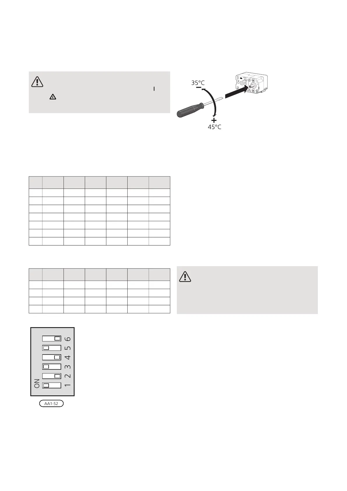
Emergency mode thermostat
The supply temperature in emergency mode is set using
a thermostat (FQ10). It can be set to 35 (pre-set, for
example underfloor heating) or 45 °C (for example radi-
ators).
LEK
LEK
För markvärme!
För frånluftsvärme!
Optional connections
MASTER/SLAVE
Several heat pumps (F1145, F1245 and F1345) can be
connected by selecting one heat pump as master and
the others as slaves.
The heat pump is always delivered as master and up to
till 8 slaves can be connected to it. In systems with
several heat pumps each pump must have a unique
name, that is only one heat pump can be ""Master" and
only one can be for example "Slave 5". Set master/slaves
in menu 5.2.1.
External temperature sensors and control signals must
only be connected to the master, except for external
control of the compressor module.
NOTE
When several heat pumps are connected to-
gether (master/slave), external return sensor
BT71 must be used. If BT71 is not connected,
the product gives a sensor fault.
Connect the communications cables as illustrated in
series to the terminal block X4:15 (A), X4:14 (B) and
X4:13 (GND) on the input card (AA3).
Use cable type LiYY, EKKX or similar.
The example shows the connection of several F1245 .
NIBE F1245Chapter 5 | Electrical connections26
 Loading...


