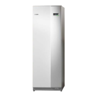
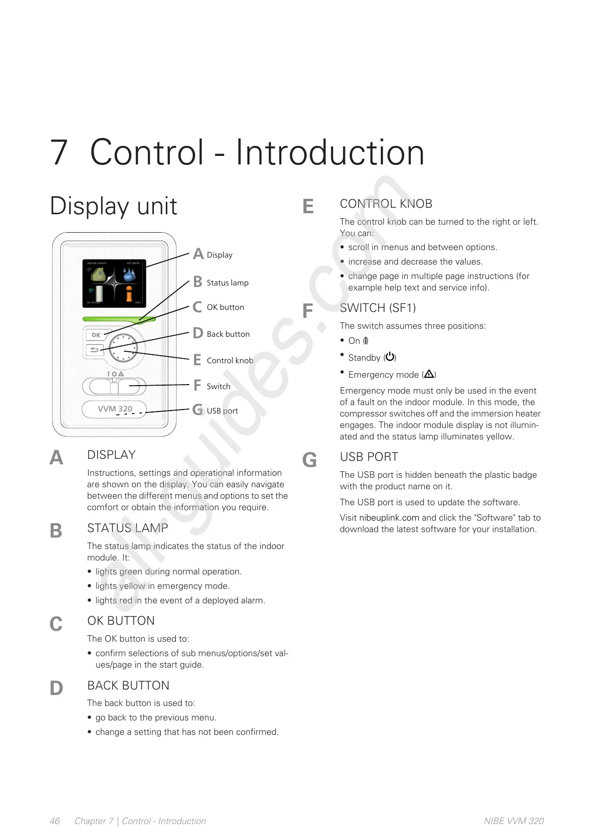
DISPLAY
Instructions, settings and operational information
are shown on the display. You can easily navigate
between the different menus and options to set the
comfort or obtain the information you require.
A
STATUS LAMP
The status lamp indicates the status of the indoor
module. It:
• lights green during normal operation.
• lights yellow in emergency mode.
• lights red in the event of a deployed alarm.
B
OK BUTTON
The OK button is used to:
• confirm selections of sub menus/options/set val-
ues/page in the start guide.
C
BACK BUTTON
The back button is used to:
• go back to the previous menu.
• change a setting that has not been confirmed.
D
CONTROL KNOB
The control knob can be turned to the right or left.
You can:
• scroll in menus and between options.
• increase and decrease the values.
• change page in multiple page instructions (for
example help text and service info).
E
SWITCH (SF1)
The switch assumes three positions:
•
On ()
•
Standby ( )
•
Emergency mode ( )
Emergency mode must only be used in the event
of a fault on the indoor module. In this mode, the
compressor switches off and the immersion heater
engages. The indoor module display is not illumin-
ated and the status lamp illuminates yellow.
F
USB PORT
The USB port is hidden beneath the plastic badge
with the product name on it.
The USB port is used to update the software.
Visit nibeuplink.com and click the "Software" tab to
download the latest software for your installation.
G
NIBE VVM 320Chapter 7 | Control - Introduction46
7 Control - Introduction
 Loading...