EasyManua.ls Logo

Nice MAESTRO200 Series User Manual

Default Icon
31 pages
To Next Page IconTo Next Page
To Previous Page IconTo Previous Page
Page #12 background image
10 – English
English
––– STEP 6 –––
6.1 - INSTALL AND CONNECT PH200 PHOTOCELLS (fig. 25)
• position each photocell 40/60 cm above the ground • position
them on the opposite sides of the zone to be protected • position
them as close as possible to the gate (maximum distance = 15 cm)
• a tube for passing the cables must be present in the fastening
point • orient the TX transmitter towards the central zone of the
RX receiver (allowed misalignment: maximum 5°)
01. Remove the front glass (Phase 01 - Fig. 25)
02. Remove the upper casing then the internal casing of the photocell
(Phase 02 - Fig. 25)
03. Perforate the lower casing in the point where the cables should pass
(Phase 03 - Fig. 25)
04. - Position the lower casing in the point where the tube for the pas-
sage of the cables arrives and mark the perforation points (Phase
04 - Fig. 25)
- Use a percussion drill to drill the wall with a 5 mm bit. Insert the 5
mm wall plugs (Phase 04 - Fig. 25)
- Pass the electrical cables through the relevant holes and fasten the
lower casing with the screws (Phase 04 - Fig. 25)
05. - Connect the electrical cable to the terminals of the TX and RX,
which must be connected in parallel to each other then connected
to the terminal on the control unit (Fig. 22). It is not necessary to
observe any polarity.
- Put back in place, in the following order, the inner casing followed
by the upper casing to be fastened with the two screws then, lastly,
insert the cover and exert slight pressure to close it (Phase 05 - Fig.
25).
1
Led SAFE
3
2
4
Ø < 5 mm
01.
03.
05.
02.
04.
25
Question and Answer IconNeed help?

Do you have a question about the Nice MAESTRO200 Series and is the answer not in the manual?

Nice MAESTRO200 Series Specifications

General IconGeneral
Motor Voltage24 V DC
Protection LevelIP44
EncoderYes
Maximum Leaf Weight400 kg
Protection RatingIP44
Power Supply230V AC
Safety FeaturesObstacle detection

Summary

STEP 1 GENERAL SAFETY WARNINGS AND PRECAUTIONS

STEP 2 PRODUCT KNOWLEDGE AND PREPARATION

PRODUCT DESCRIPTION AND INTENDED USE

Describes the product, its purpose, and limitations for residential use.

DEVICES REQUIRED FOR FULL SYSTEM

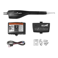
Lists all necessary devices for a complete automation system.

STEP 3 PRELIMINARY INSTALLATION WORK

CHECK GATE SUITABILITY AND ENVIRONMENT

Ensures gate mechanics and environment are suitable for automation.

PRODUCT APPLICATION LIMITS

Details gate leaf dimensions, weight, and environmental limits for product use.

PRODUCT DURABILITY ESTIMATION

Explains how to estimate product lifespan based on usage and conditions.

STEP 4 PRE-INSTALLATION WORKS

WORKS PRIOR TO INSTALLATION

Establishes the positioning of system devices and preparatory site work.

ELECTRICAL CABLES PREPARATION

Guides the preparation of all electrical connection cables according to specifications.

STEP 5 COMPONENT ASSEMBLY AND CONNECTION

GEARMOTOR INSTALLATION PROCEDURE

Details the physical mounting and securing of the gearmotor unit.

ADJUSTING OPENING MECHANICAL LIMIT SWITCH

Explains how to set mechanical limits for gate opening if no external stops are present.

GEARMOTOR ELECTRICAL CONNECTION

Provides instructions for making the electrical connections to the gearmotor.

STEP 6 ACCESSORY INSTALLATION

INSTALL AND CONNECT PHOTOCELLS

Guides the installation and wiring of the PH200 photocell safety devices.

INSTALL AND CONNECT FLASHING INDICATOR

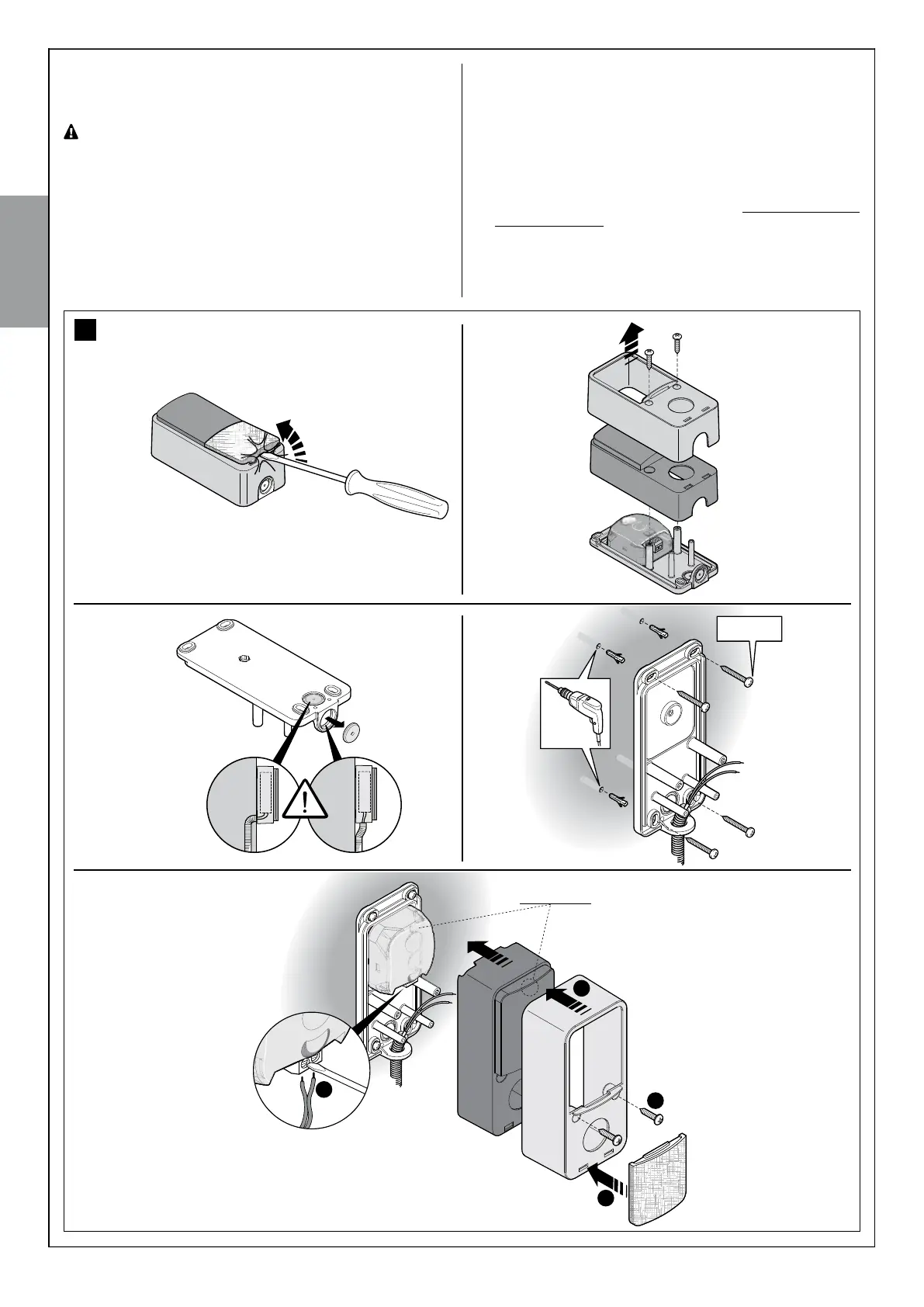
Instructs on installing and connecting the FL200 flashing indicator light.

STEP 7 PROGRAMMING THE AUTOMATION

POWER SUPPLY CONNECTION

Explains how to properly connect the automation to the main power supply.

PRELIMINARY CHECKS

Guides initial electrical checks before proceeding with programming.

CONNECTED DEVICES RECOGNITION

Describes the process for the control unit to recognize connected devices.

GATE LEAF OPEN AND CLOSURE ANGLES RECOGNITION

Details how the system learns the gate's opening and closing limits.

RADIO TRANSMITTERS CHECK

Explains how to verify the functionality of radio transmitters.

ADJUSTMENTS FOR GATE OPERATION

Covers selection of leaf speed and operating cycle types for gate automation.

STEP 8 TESTING AND COMMISSIONING

SYSTEM TESTING PROCEDURES

Outlines the essential tests for safety and functionality after installation.

COMMISSIONING THE AUTOMATION

Details the final steps for putting the automation system into operation.

STEP 9 MAINTENANCE AND DISPOSAL

PRODUCT DISPOSAL GUIDELINES

Provides guidelines for the proper disposal of the product.

STEP 10 FURTHER DETAILS

ADVANCED ADJUSTMENTS

Explains how to adjust operating parameters using the radio transmitter.

OPTIONAL ACCESSORIES

Lists and describes optional accessories for system integration.

DEVICES ADDITION OR REMOVAL

Guides on adding or removing compatible devices from the system.

RADIO TRANSMITTERS MEMORISATION

Details the procedure for memorizing radio transmitters with the control unit.

TROUBLESHOOTING COMMON ISSUES

Provides solutions for common malfunctions and errors encountered with the system.

DIAGNOSTICS AND SIGNALS

Explains special signals from devices to recognize operating status or malfunctions.

TECHNICAL SPECIFICATIONS

Related product manuals