English – 21
English
desired key for memorisation on the selector switch for at least 3 s.
If the procedure was memorised correctly, the P1 led will ash slowly
3 times.
04. After 10 s the memorisation phase terminates automatically.
Deletion – if the DS100 selector switch is memorised in Mode 1, one
deletion phase is sufcient and at step 3 any key, A, B or C, can be
pressed. If the selector is memorised in Mode 2 a deletion phase is nec-
essary for each key stored.
To delete DS100:
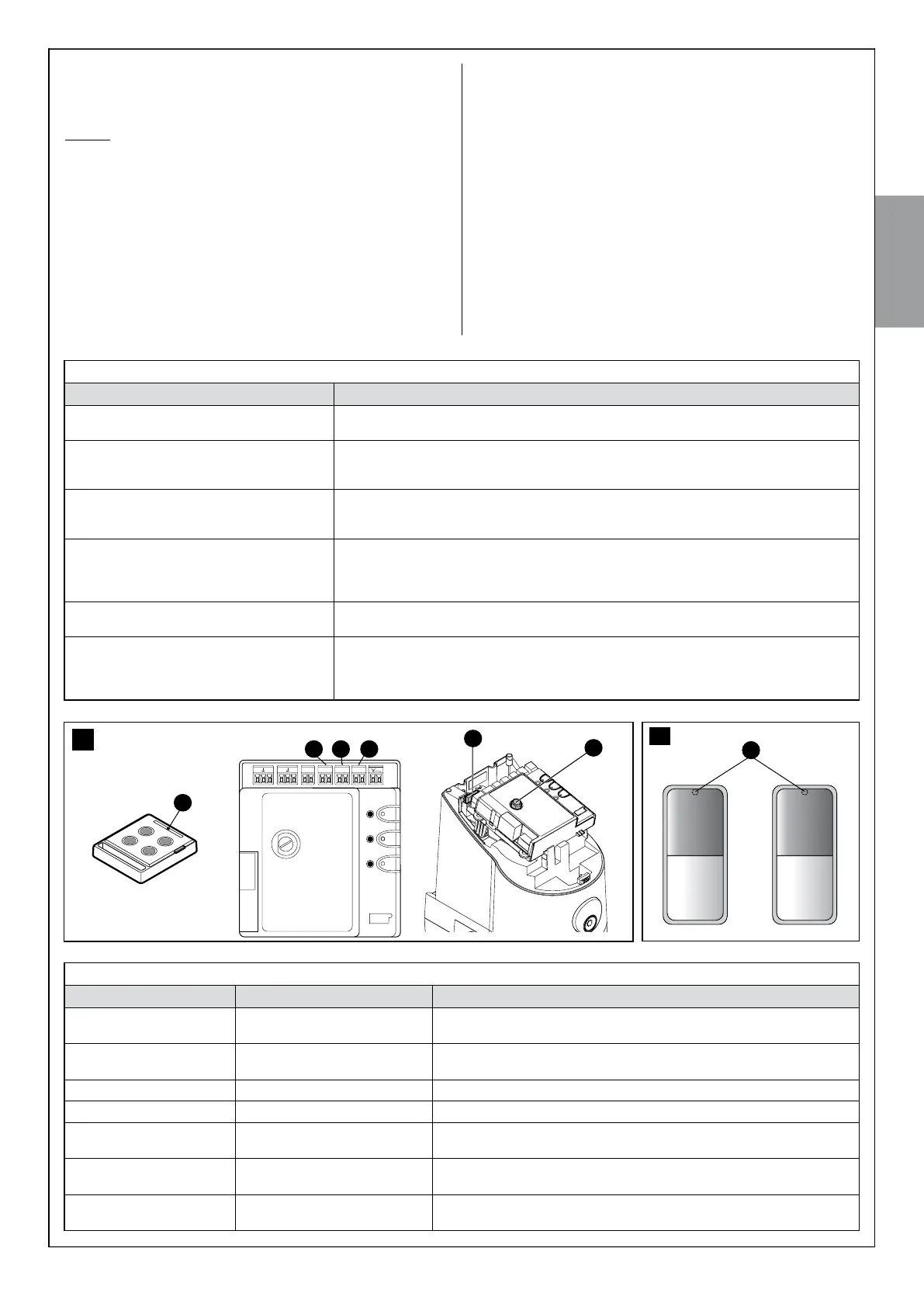
01. Press P1 (g. 36) on the control unit and hold it down.
02. Wait until the P1 led lights up, within three seconds.
03. Type in the factory combination 11 (or the secret combination, if the
factory combination has been changed), and press the desired key
for deletion on the selector switch for at least three seconds. If can-
cellation was successful the P1 led will ash quickly ve times.
04. If there are other selector switches to delete, keeping P1 depressed,
repeat step 3 within another 10 seconds; otherwise, the deletion will
stop automatically.
For more information on the DS100 selector switch, refer to the product
instruction manual, or visit www.niceforyou.c om
10.5 - TROUBLESHOOTING
Table 10 contains instructions to help you solve malfunctions or errors
that may occur during the installation stage or in case of failure.
10.6 - DIAGNOSTICS AND SIGNALS
A few devices give out special signals that allow you to recognise the
operating status or possible malfunctions.
10.6.1 - Photocells
In the photocells, there is a SAFE led [A] (fig. 38) which allows you to
check the operating state at any time, see Table 11.
TX RX
38
E
F
37
A
CB D
MMM M
FLASHBUS STOP SbS
A
TABLE 10 (fig. 37)
Symptoms Probable cause and possible solution
The radio transmitter is not emitting a signal (the
led [A] is not lit)
• Check to see if the batteries are spend. Replace if necessary (see paragraph 11.4)
The manoeuvre does not start and the led
“ECSBbus” [B] does not flash
• Make sure that the power supply cable is properly inserted into the electrical network socket
• Check to see if the fuses [E] or [F] are blown; if necessary, identify the reason for the failure and
then replace the fuses with others of equal value
No manoeuvre starts and the flashing light is off • Make sure that the commands are actually received. If the command is delivered to the SbS
input the relative “SbS” led [D] must light up; otherwise if the radio transmitter is used, the “ECS-
bus” led flashes slowly twice
No manoeuvre starts and the flashing light
flashes a few times
• Check that the STOP input is active, that is, the led “STOP” [C] is lit. If this does not happen,
check the device connected to the STOP input
• The photocells test which is carried out at the start of each manoeuvre has not given a positive
result; check them, referring also to compliance with Table 11
The manoeuvre starts but it is immediately fol-
lowed by a reverse run
• The selected force could be too low for this type of gate. Check to see whether there are any
obstacles; if necessary increase the force as described on paragraph 10.1.1)
The manoeuvre is carried out but the flasher
does not work
• Make sure that there is voltage on the flashing light’s FLASH terminal during the manoeuvre
(being intermittent, the voltage value is not important: approximately 10-30 Vac); if there is volt-
age, the problem is due to the lamp; in this case replace the lamp with one having the same
characteristics
TABLE 11
“SAFE” led [A] - fig. 38 Status Action
Off The photocell has no power supply
or is faulty
Check that on the terminals of the photocell there is a voltage of approximately
8-12 Vdc; if the voltage is correct, it is likely that the photocell is faulty.
3 quick flashes and 1 second
pause
Device not recognised by control
unit
Repeat the recognition procedure on the control unit. Check that all photocell
pairs on the ECSbus have different addresses (see Table 8)
1 very slow flash The RX is receiving optimum signal Normal operation
1 slow flash The RX is receiving good signal Normal operation
1 quick flash The RX is receiving poor signal Normal operation but it is necessary to check the TX-RX alignment and correct
cleaning of the glasses
1 very quick flash The RX is receiving bad signal It is at the limit of normal operation. It is necessary to check the TX-RX align-
ment and correct cleaning of the glasses
Always on The RX is receiving no signal Check for any obstruction between TX and RX. Check that the led on TX emits
a slow flashing. Check the TX-RX alignment
 Loading...