2.5 - Initial start-up and electrical connections
,03257$17t&RQQHFWLRQVPXVWEHPDGHH[FOXVLYHO\E\TXDOLƄHGSHU-
sonnel.
ESDQONVDQHMFTOSGDBNMSQNKTMHSBGDBJSG@S@KKSGD+$#Rk@RGQ@OHCKXENQ@EDV
seconds, then perform the following checks:
1."GDBJSG@SSGDQDHR@UNKS@FDNE@OOQNWHL@SDKX5CBNMSDQLHM@KR(E
not, unplug the unit immediately and carefully check the connections and
input voltage.
2. ESDQHMHSH@KKXk@RGHMFQ@OHCKXSGD/+$#VHKKHMCHB@SDSGDBNMSQNKTMHSHRVNQJ-
HMFBNQQDBSKXAXk@RGHMFQDFTK@QKX@SRDBNMCHMSDQU@KR6GDMSGDQDHR@U@QH-
@SHNMHMSGDHMOTSRSGDf/tKDCVHKKQ@OHCKXk@RGSVHBDSNRGNVSG@SSGDHMOTS
has been recognised.
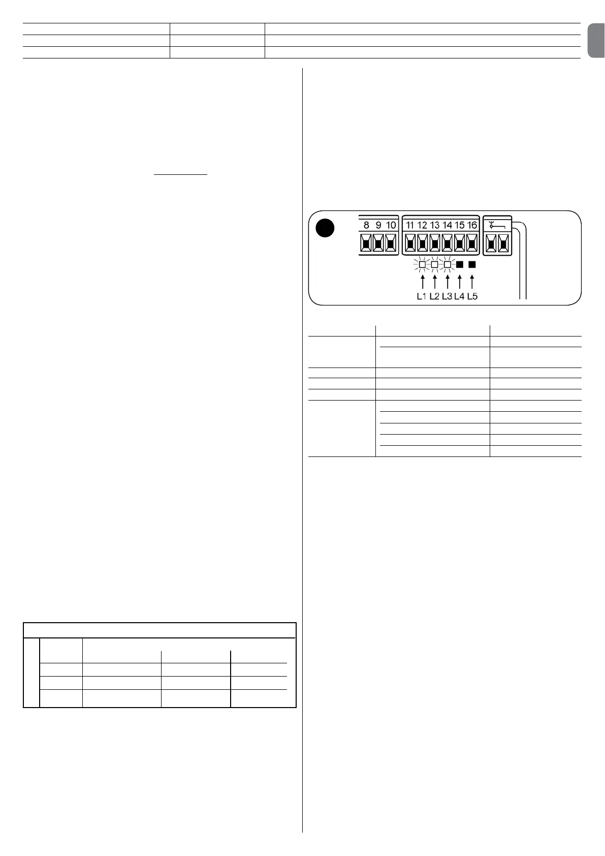
3. If the connections are correct, the LED for the “NC”-type inputs will be on,
VGHKDSGNRDENQSGDf-.tSXODHMOTSRLTRSADNEE2DDƄJ$ and Table 2.
TABLE 2
INPUT INPUT TYPE STATUS LED
23./ 23./-" +.M
".-23 -31$2(23 -"$ +.M
23./*Ƅ
/'.3. -" +.M
%.3. -" +.M
23$/!823$/ -. +.EE
47 ./$-/ 13( ++8SXOD-. +.EE
./$-/ 13( ++8SXOD-. +.EE
./$-.-+8-. +.EE
"+.2$.-+8-. +.EE
%.3.-" +.M
4. Check that the relative LEDs switch on and off when the devices connected
to the inputs are operated.
5. Check that by pressing P2 both motors perform a short opening manoeuvre,
@MCSGDLNSNQNESGDTOODQKD@ERS@QSRjQRS!KNBJSGDL@MNDTUQDAXOQDRR-
ing P2 again. If the motors do not start up for opening, invert the polarities
NESGDLNSNQB@AKDR(EGNVDUDQSGDjQRSNMDSNLNUDHRMNSSGDTOODQKD@E
operate jumper E (ƄJ
2.6 - Automatic search system for the limit switches
.MSGDRTBBDRRETKBNLOKDSHNMNESGDU@QHNTRBNMSQNKRRS@QSSGD@TSNL@SHBRD@QBG
RXRSDLOG@RDENQSGDKHLHSRVHSBGDR3GHRVNQJHRMDBDRR@QX@RSGD,"BNM-
trol unit must “measure” how long the opening and closing manoeuvres take
3GHROQNBDCTQDHRBNLOKDSDKX@TSNL@SHB@MCCDSDBSRSGDLDBG@MHB@KNODMHMF
and closing stops by measuring the load on the motors.
Warning! – If this procedure has already been carried out, in order to
UHDFWLYDWHLWWKHXVHUPXVWƄUVWGHOHWHWKHPHPRU\VHHWKHq0HPRU\
de letion” chapter). In order to check whether the memory contains any
li mit switch parameters, turn the power supply to the control unit on
and then off again.,IDOOWKH/('VƅDVKUDSLGO\IRUDSSUR[LPDWHO\VHF-
RQGVWKHPHPRU\LVHPSW\,IKRZHYHUWKH\RQO\ƅDVKIRUVHFRQGV
the memory already contains some limit switch parameters.
Before starting limit switch searching, make sure that all the safety devices
@QDDM@AKDC23.//'.3.@MC/'.3.3GDOQNBDCTQDVHKKADHLLDCH@SDKX
interrupted if a safety device triggers or a command arrives. The leafs MUST
EHSRVLWLRQHGDWDSSUR[LPDWHO\PLGWUDYHO
3URFHGXUHt3UHVVWKH3EXWWRQƄJWRVWDUWEHJLQVHDUFKLQJZKLFK
includes:
!NSGLNSNQRNODMAQHDkX
- Motor closes the lower leaf until it reaches the mechanical closing stop.
3GDTOODQKD@ELNSNQBKNRDRTMSHKHSQD@BGDRSGDLDBG@MHB@KBKNRHMFRSNO
3GDLNSNQNESGDTOODQKD@EADFHMRSNNODM
- After the programmed delay, opening of the lower leaf begins. If the delay
HRHMRTEjBHDMSAKNBJSGDRD@QBGAXOQDRRHMF/ƄJSGDMLNCHEXSGDSHLD
RDDBG@OSDQ
3GDBNMSQNKTMHSLD@RTQDRSGDLNUDLDMSQDPTHQDCENQSGDLNSNQRSNQD@BGSGD
opening mechanical stops.
"NLOKDSDBKNRHMFL@MNDTUQD3GDLNSNQRB@MRS@QS@SCHEEDQDMSSHLDRSGD@HL
is to prevent the leafs from shearing by maintaining a suitable delay.
English – 3
2.4.1 - Notes about connections
Most connections are extremely simple and many of them are direct connec-
SHNMRSN@RHMFKDTRDQONHMSNQBNMS@BS3GDENKKNVHMFjFTQDRRGNVDW@LOKDRNE
how to connect external devices:
s(YHU\WKLQJLQVWDQGE\3KRWRWHVWFRQQHFWLRQ
3GDf$UDQXSGHMFHMRS@MCAXtETMBSHNMHR@BSHUD@RRS@MC@QC(SHRDWBKTCDC@TSN-
matically only when the Phototest function is activated. Note - The “Everything
in stand by” and Phototest functions are alternatives as one excludes the other.
3GDf$UDQXSGHMFHMRS@MCAXtETMBSHNM@KKNVRBNMRTLOSHNMRSNADQDCTBDC3GQDD
types of connections can be obtained:
- with “Everything in stand by” active (HQHUJ\VDYLQJRDDDKDBSQHB@KCH@FQ@LHM
ƄJD
RS@MC@QCBNMMDBSHNMVHSGNTSf$UDQXSGHMFHMRS@MCAXt@MCVHSGNTSf/GNSNSDRSt
see electrical diagram in ƄJE
VHSGNTSf$UDQXSGHMFHMRS@MCAXt@MCVHSGf/GNSNSDRStRDDDKDBSQHB@KCH@FQ@LHM
ƄJF
6GDMSGDf$UDQXSGHMFHMRS@MCAXtETMBSHNMHR@BSHUDLHMTSD@ESDQSGDDMCNE
a manoeuvre the control unit goes into “Everything in stand by”, turning off the
(MOTSR@MC.TSOTSRSNQDCTBDBNMRTLOSHNMR3GDRS@STRHRHMCHB@SDCAXSGDf.*t
+$#VGHBGADFHMRSNk@RGLNQDRKNVKXWARNING – If the control unit is powered
EQNL@OGNSNUNKS@HBO@MDKf2NKDLXNtRXRSDLNQ@ATEEDQA@SSDQXSGDf$UDQXSGHMFHM
stand by” function must be activated as shown in the electrical diagram in ƄJD.
6GDMSGDf$UDQXSGHMFHMRS@MCAXtETMBSHNMHRMNSQDPTHQDCSGDf/GNSNSDRStETMB-
SHNML@XAD@BSHU@SDC3GHRUDQHjDR@SSGDADFHMMHMFNE@L@MNDTUQDSG@SSGD
BNMMDBSDCOGNSNBDKKRNODQ@SDBNQQDBSKX3NTRDSGHRETMBSHNMjQRSBNMMDBSSGD
photocells appropriately (see electrical diagram in ƄJF@MCSGDM@BSHU@SDSGD
function. Note – When the phototest is activated, the inputs subjected to the
test procedure are PHOTO, PHOTO1 and PHOTO2. If one of these inputs is not
used it must be connected to terminal no. 8.
• Key switch connection
([DPSOHƄJD'NVSNBNMMDBSSGDRVHSBGHMNQCDQSNODQENQLSGD23$/
!823$/@MC23./ETMBSHNMR
([DPSOHƄJE'NVSNBNMMDBSSGDRVHSBGHMNQCDQSNODQENQLSGD23$/
!823$/@MCNMDNESGD@TWHKH@QXHMOTSETMBSHNMR/ 13( +./$-(-&./$-
.-+8"+.2$.-+8v
Note – For electrical connections with the “Everything in stand by” function
active, see “Everything in stand by/Phototest function” in this paragraph 2.4.1.
s&RQQHFWLRQIRU*DWH2SHQ,QGLFDWRU(OHFWULFORFNƄJ
If the gate open indicator has been programmed, the output can be used as an
NODMF@SDHMCHB@SNQKHFGS3GDKHFGSk@RGDRRKNVKXCTQHMFNODMHMF@MCPTHBJKX
CTQHMFBKNRHMF(EHSHRNMATSCNDRMNSk@RGSGHRHMCHB@SDRSG@SSGDF@SDHRNODM
If the light is off, the gate is closed. Se the output has been programmed as an
electric lock, it is activated for 3 seconds each time opening begins.
2.4.2 - STOP type input
3GD,"BNMSQNKTMHSB@MADOQNFQ@LLDCENQSVNSXODRNE23./HMOTS
- NC type STOP for connecting up to NC type contacts.
- Constant resistance STOP. It enables the user to connect up to the con-
SQNKTMHSNECDUHBDRVHSGJƄBNMRS@MSQDRHRS@MBDDFRDMRHSHUDDCFDR
3GDHMOTSLD@RTQDRSGDU@KTDNESGDQDRHRS@MBD@MCCHR@AKDRSGDL@MNDTUQD
when the resistance is outside the nominal value. Devices with normally open
f-.tNQMNQL@KKXBKNRDCf-"tBNMS@BSRNQLTKSHOKDCDUHBDRDUDMNECHEEDQDMS
SXODRB@MADBNMMDBSDCSNSGDBNMRS@MSQDRHRS@MBD23./HMOTSOQNUHCDC
SG@S@OOQNOQH@SD@CITRSLDMSR@QDL@CDRDD3@AKD
WARNING! – If the constant resistance STOP input is used to connect
GHYLFHVZLWKVDIHW\IXQFWLRQVRQO\WKHGHYLFHVZLWK.ŭFRQVWDQW
will resistance output guarantee the fail-safe category 3.
Notes to Table 1:
Note 1 – Any number of NO devices can be connected to each other in paral-
OHOZLWKDQ.ŭWHUPLQDWLRQUHVLVWDQFH (ƄJD). For electrical connections
with the “Everything in stand by” function active, see “Everything in stand by/
Phototest function” in this paragraph 2.4.1.
Note 2 – The NO and NC combination can be obtained by placing the two con-
WDFWVLQSDUDOOHODQGSODFLQJDQ.ŭUHVLVWDQFHLQVHULHVZLWKWKH1&FRQWDFW,W
LVWKHUHIRUHSRVVLEOHWRFRPELQHGHYLFHV121&DQG.ŭƄJE).
Note 3 – Any number of NC devices can be connected in series to each other
DQGWRDQ.ŭUHVLVWDQFHƄJF).
Note 4 t2QO\RQHGHYLFHZLWKDQ.ŭFRQVWDQWUHVLVWDQFHRXWSXWFDQEH
connected; multiple devices must be connected “in cascade” with a single 8.2
.ŭWHUPLQDWLRQUHVLVWDQFHƄJG).
A
RSCDUHBDSXOD
NO NC 8,2 Kŭ
In parallel (note 1 note 2 (MO@Q@KKDK
NC (note 2 (MRDQHDRnote 3 (MRDQHDR
.ŭ In parallel In series (note 4
TABLE 1
second device type:
"+.2$ -. .MKXB@QQHDRNTSSGDBKNRHMFL@MNDTUQD
/'.3. NC /'.3.ETMBSHNM
DISABLED — No function
EN

 Loading...


