5
GB
2.3.2) Description of connections
Here follows a brief description of the possible control unit output connections:
Terminals Function Description
L-N- Power supply line mains power supply
1÷3 Motor 2 * M2 motor connection
4÷5 Flashing light Connection of flashing light 24Vd.c. max. 25W
6÷7 Open Gate indicator/Elect.Lock Connection for Open Gate Indicator 24Vac max. 5W or Electric lock
12V max. 25VA please refer to the “Programming” chapter)
8 24Vdc/Phototest Power Supply +24V TX photocells for phototest (max. 100mA)
9 0Vdc 0V Power supply for services
10 24Vdc Power input for services, RX photocells, etc. (24Vac max. 200mA)
11 Common Common for all inputs (+24Vdc)
12 STOP **Input with STOP function (emergency, safety shutdown)
13 PHOTO NC Input for safety devices (photocells, sensitive edges)
14 PHOTO1 Input NC for safety devices (photocells, sensitive edges)
15 STEP-BY-STEP Input for cyclical functioning (OPEN-STOP-CLOSE-STOP)
16 AUX *** Auxiliary input
17÷18 Aerial Connection for the radio receiver aerial
* This is not used for single leaf gates (the control unit automatically recognises if only one motor has been installed).
** The STOP input can be used for “NC” or constant resistance 8,2kΩ contacts (please refer to the “Programming” chapter)
*** The auxiliary input AUX may be programmed in one of the following functions:
Function Input type Description
PARTIAL OPEN TYPE 1 NO Fully opens the upper leaf
PARTIAL OPEN TYPE 2 NO Opens the two leaf half way
OPEN NO Only carries out the opening manoeuvre
CLOSE NO Only carries out the closing manoeuvre
PHOTO 2 NC PHOTO 2 function
DISABLED - - No function
Unless otherwise programmed, the AUX input performs the Partial Open TYPE 1 function
Most connections are extremely simple and many of them are direct
connections to a single user point or contact.
The following figures show examples of how to connect external
devices.
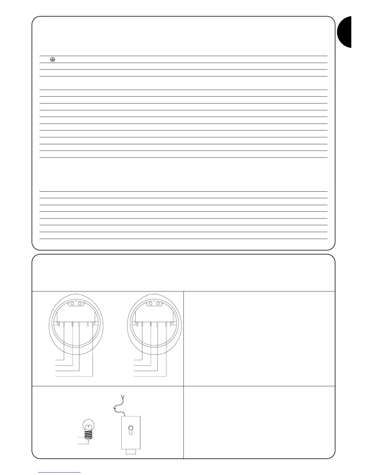
2.3.3) Notes about connections
Key switch connection
Example 1
How to connect the switch in order to perform the STEP-BY-STEP
and STOP functions.
Example 2
How to connect the switch in order to perform the STEP-BY-STEP
function and one of the auxiliary input functions (PARTIAL OPENING,
OPEN ONLY, CLOSE ONLY …).
Connection for Gate Open Indicator/Electric lock
If the gate open indicator has been programmed, the output can be
used as an open gate indicator light. It flashes slowly during open-
ing, and quickly during closing. If it is on but does not flash, this indi-
cates that the gate is open. If the light is off, the gate is closed. If the
electric lock has been programmed, the output can be used as an
electric lock. The electric lock will activate for 3 seconds each time
opening begins.
 Loading...