English – 19
1. Press the key [Set] and hold it down (approx. 3 s)
3s
2. Release the [Set] key when L1 LED starts flashing
L1
3. Press key [s] or [t] to move the flashing LED onto the input LED L7
representing the “Maintenance warning” parameter or L7
4. Press the key [Set],and hold it down during step 5, 6 and 7
5. Wait approx. 3 seconds, after which the LED representing the current
level of the parameter “Maintenance warning” will light up 3s
6. Press and immediately release the [s] and [t] keys.
and
7. The LED that corresponds to the selected level flashes. The number of flashes indicates the percentage
of manoeuvres performed(in multiples of 10%) in relation to the set limit.
For example: with the maintenance warning set on L6 being 10000, 10% is equal to 1000 manoeuvres;
if the LED flashes 4 times, this means that 40% of the manoeuvres have been reached (being between
4000 and 4999 manoeuvres). The LED will not flash if 10% of the manoeuvres hasn’t been reached.
8. Release the key [Set]
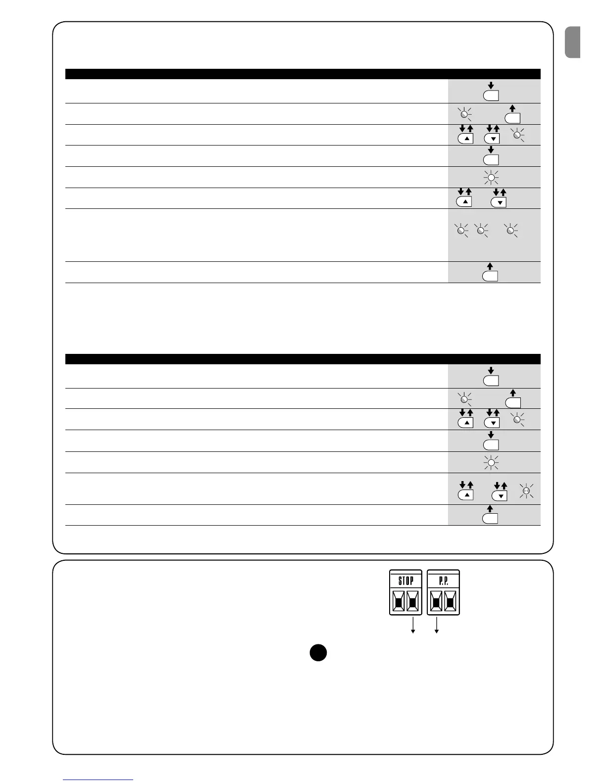
Control of the number of manoeuvres performed
The number of manoeuvres performed as a percentage on the set limit can be verified by means of the “Maintenance warning” function.
Follow the indications in table 15 for this control.
Table 15: control of the number of manoeuvres performed Example
SET
SET
SET
SET
.... n=?
Manoeuvre counter reset
After the maintenance of the system has been performed the manoeuvre counter must be reset. Proceed as described in table 16.
1. Press the key [Set] and hold it down (approx. 3 s)
3s
2. Release the [Set] key when L1 LED starts flashing
L1
3. Press key [s] or [t] to move the flashing LED onto the input LED L7 representing the
“Maintenance warning” parameter or L7
4. Press the key [Set], and hold it down during step 5 and 6
5. Wait approx. 3 seconds, after which the LED representing the current
level of the parameter “Maintenance warning” will light up. 3s
6. Press keys [s] and [t], hold them down for at least 5 seconds and then release them.
The LED that corresponds to the selected level flashes rapidly indicating that the
manoeuvre counter has been reset
and
7. Release the key [Set]
Table 16: manoeuvre counter reset Example
SET
SET
SET
SET
7.5 Connection of Other Devices
If the user needs to feed external devices such as a proximity reader
for transponder cards or the illumination light of the key-operated
selector switch, it is possible to tap power as shown in Figure 27.
The power supply voltage is 24Vdc -30% - +50% with a maximum
available current of 100mA.
- +
24Vcc
27
 Loading...