English – 21
BLUEBUS LED Cause ACTION
STOP LED Cause ACTION
STEP-BY-STEP LED Cause ACTION
OPEN LED Cause ACTION
Off
ACTION
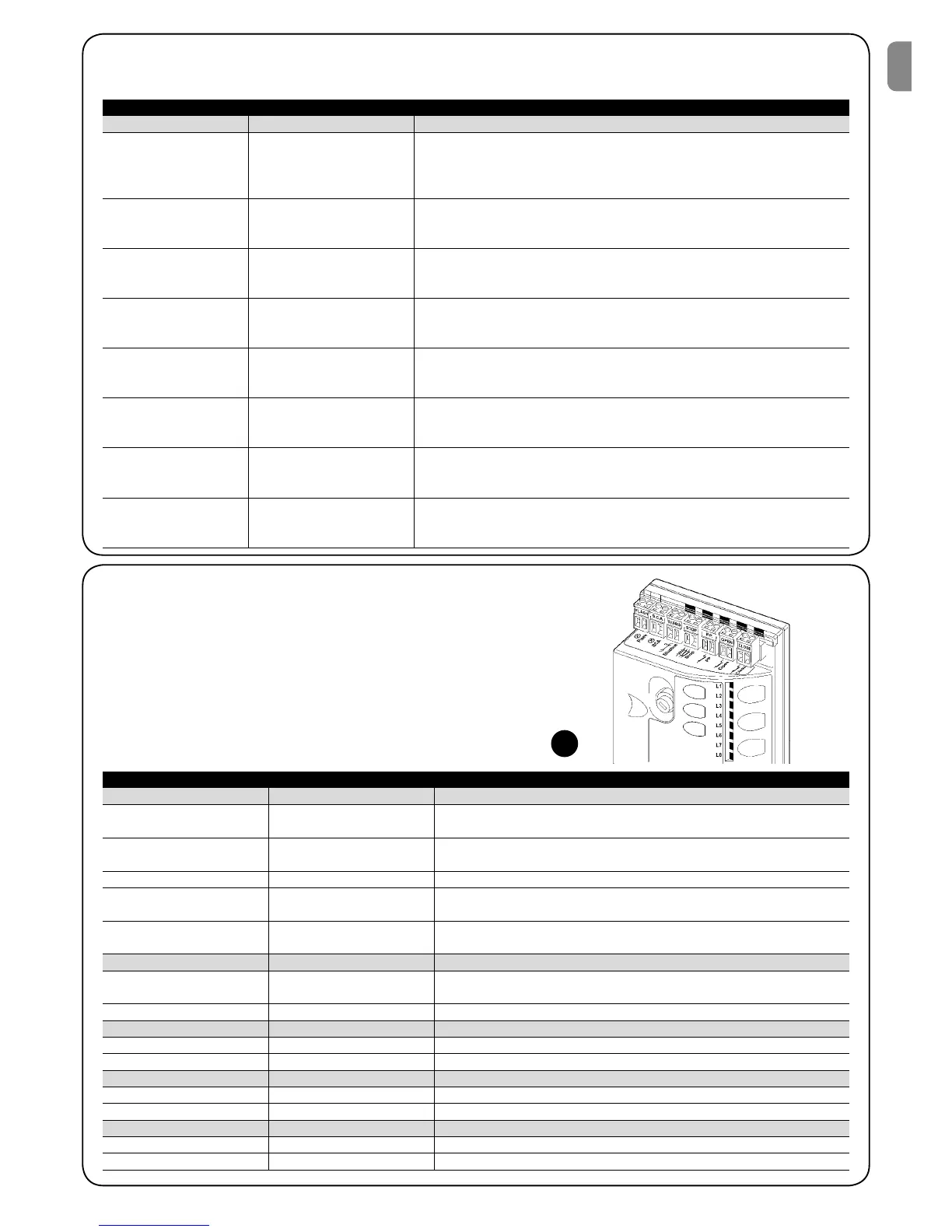
7.7.2) Signals on the control unit
On the ROBUS350 control unit there is a set of LED’s each of which
can give special indications both during normal operation and in
case of malfunctions.
Table 20: LED’s on the control unit’s terminals
Malfunction
Make sure there is power supply; check to see if the fuses are blown; if necessary, identify the rea-
son for the failure and then replace the fuses with others having the same characteristics replaced
On Serious malfunction
There is a serious malfunction; try switching off the control unit for a few seconds; if the condi-
tion persists it means there is a malfunction and the electronic board has to be replaced
One flash every second Everything OK Normal operation of control unit
2 quick flashes
The status of the inputs has
changed
This is normal when there is a change in one of the inputs: STEP-BY-STEP,
STOP, OPEN, CLOSE, triggering of photocells or the radio transmitter is used
Series of flashes separated by
a second’s pause
Miscellaneous It corresponds to the flashing light’s signal. See table n° 21.
Off
ACTION
Activation of the STOP input Check the devices connected to the STOP input
On Everything OK STOP Input active
Off Everything OK input not active
On
Off
Activation of the STEP-BY-STEP input
Everything OK
This is normal if the device connected to the STEP-BY-STEP input is actually active
OPEN input not active
On
Activation of the OPEN input
This is normal if the device connected to the OPEN input is actually active
CLOSE LED Cause ACTION
Off Everything OK CLOSE input not active
On
Activation of the CLOSE input
This is normal if the device connected to the CLOSE input is actually active
29
6 flashes
1 second’s pause
6 flashes
At the starting of the manoeuvre, the devices connected to BLUEBUS do not
correspond to those recognized during the recognition phase. One or more
devices may be faulty; check and, if necessary, replace them; in case of modi-
fications repeat the recognition process (7.3.4 Recognition of Other Devices).
7.7.1) Flashing light signalling
During the manoeuvre the flashing light FLASH flashes once every second. When something is wrong the flashes are more frequent; the light
flashes twice with a second’s pause between flashes.
Table 19: FLASH flashing light signalling
Quick flashes Cause ACTION
1 flash
1 second’s pause
1 flash
BLUEBUS error
2 flashes
1 second’s pause
2 flashes
Triggering of a photocell
At the starting of the manoeuvre, one or more photocells do not enable it;
check to see if there are any obstacles.
This is normal when there is an obstacle impeding the movement.
3 flashes
1 second’s pause
3 flashes
Activation of the “motor for-
ce” limiting device
During the movement, the gate experienced excessive friction; identify the
cause.
4 flashes
1 second’s pause
4 flashes
Activation of the STOP input
At the starting of the manoeuvre or during the movement, the STOP input was
activated; identify the cause
5 flashes
1 second’s pause
5 lampeggi
Error in the internal parame-
ters of the electronic control
unit
Wait at least 30 seconds, then try giving a command. if the condition persists it
means there is a malfunction and the electronic board has to be replaced
The maximum manoeuvre
limit/hour has been excee-
ded.
Wait for a few minutes until the manoeuvre limiting device drops to under the
maximum limit
7 flashes
1 second’s pause
7 flashes
8 flashes
1 second’s pause
8 flashes
here is an error in the inter-
nal electric circuits
A command that does not
permit other commands to be
performed is already present.
Disconnect all the power circuits for a few seconds and then try to give the
command again. if the condition persists it means there is a serious malfunc-
tion and the electronic board has to be replaced
Check the type of command that is always present; for example, it could be a
command from a timer on the “open” input.
 Loading...