ENGLISH – 5
3.5 PRE-INSTALLATION WORKS
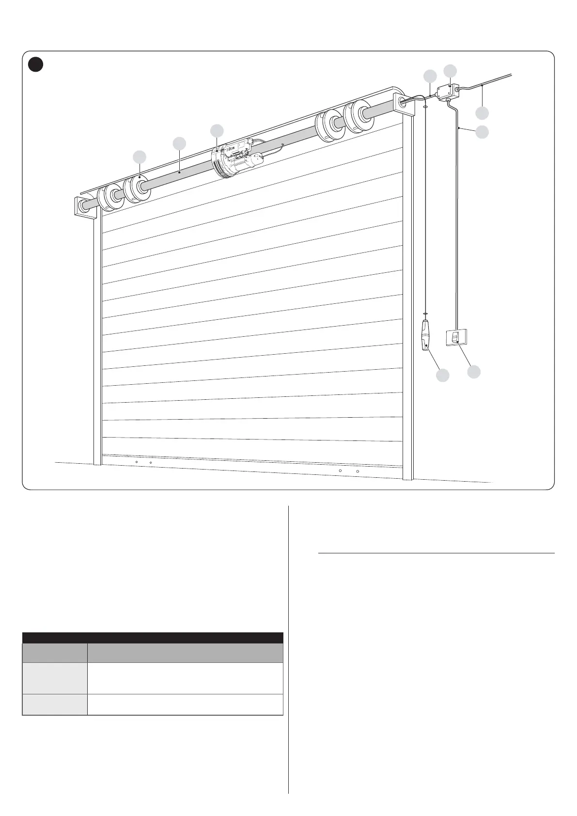
The gure shows an example of an automation system, constructed using Nice components.
A
B
C
D
3
1
2
F
E
4
A Spring support box
B Spring support shaft
C Gearmotor
D Junction box
E Locking/unlocking knob
F Command inverter
The above-mentioned components are positioned according to a
typical standard layout. Using the layout shown in "Figure 4" for
reference, dene the approximate position in which each compo-
nent of the system will be installed.
Table 1
TECHNICAL SPECIFICATIONS OF ELECTRICAL CABLES
Identication
no.
Cable characteristics
1
GEARMOTOR POWER SUPPLY cable
1 cable 4 x 0.75 mm
2
Maximum length 30 m [note 1]
2
PUSHBUTTON PANEL cable
1 cable 3 x 0.75 mm
2
minimum
Note 1 If the power supply cable is longer than 30 m, a cable with
larger cross-sectional area (3 x 2.5 mm
2
) must be used
and a safety earthing system must be installed near the
automation.
a
The cables used must be suited to the type of envi-
ronment of the installation site.
 Loading...