8 – ENGLISH
A
B
Ø 12 mm
13
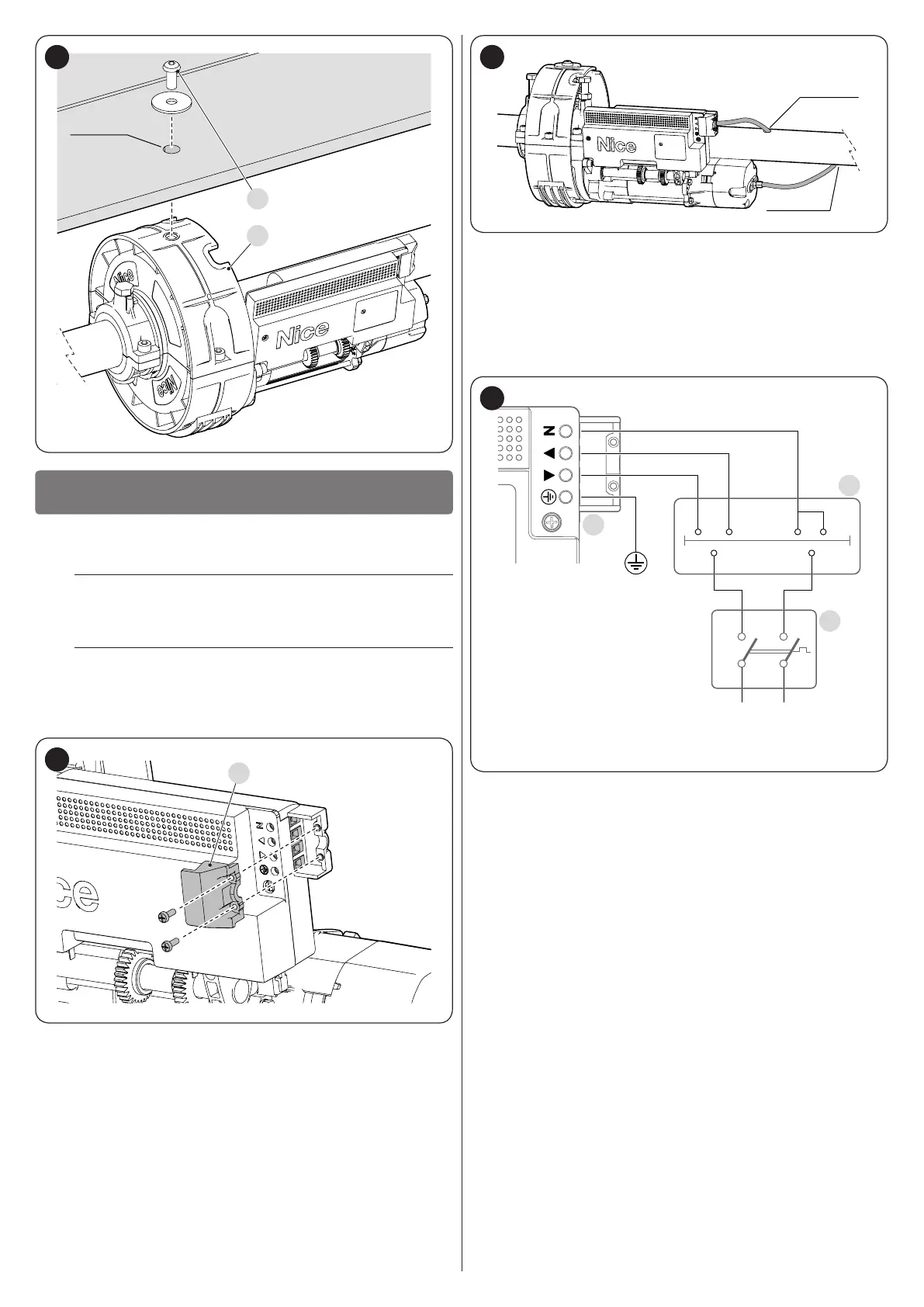
ELECTRICAL CONNECTIONS
4
4 ELECTRICAL CONNECTIONS
4.1 PRELIMINARY CHECKS
f
All electrical connections must be made with the
system disconnected from the mains electricity and
with the back-up battery (if present) disconnected.
a
The connection operations must only be carried out
by qualied personnel.
To make the electrical connections:
1. remove the screws and the protective cover (A)
A
14
2. pass the power cable through the hole cut previously on the
spring support shaft
3. if the gearmotor is equipped with an electric brake, t the
brake sheath through the second hole on the spring support
shaft
Ø
15
4. make the connections by following the scheme shown in
"Figure 16"
5. after making the connections, lock the power cable by
screwing the protective cover (A) in place.
4.2 WIRING DIAGRAM AND DESCRIPTION OF
CONNECTIONS
NL
230 Vac
B
A
C
16
A Mains power inputs terminal
B Manual command buttons
C Omnipolar device
 Loading...