4 – English
GB
CONTROL and CONNECTION ELEMENTS
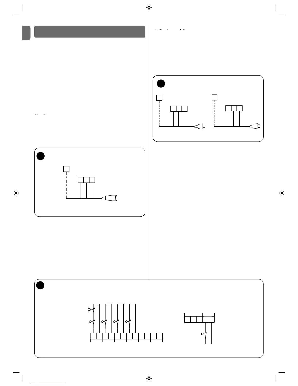
Connection of the three-phase power supply cable
16A EEC plug is connected to terminals L1, L2, L3 and the PE
terminal
n this case it is possible to remove the EE
assembly.
Control elements
It is possible to control door OPENING and CLOSING with the
buttons built into the cover in automatic and/or deadman mode.
If set in automatic mode, the door can be stopped at any time with
the STOP button.
It is possible to connect other control elements for control from the
outside, a triple button for example.
A switch with a cable coming down from the ceiling, installed inside
or outside, controls the door in the OPEN-STOP-CLOSE function.
If the optional radio receiver is connected, it is always possible to
stop the door with the manual radio transmitter.
Direction of rotation control
If the door is in the lower fi nal position, now it is necessary to open
it by about 50cm with the handle to prevent the track ropes from
coming out of their housing (sectional doors) or excessive winding of
the rolling shutter in the case of rotation is reversed.
OWN buttons. It is necessary to disconnect the EEC plug and
everse the U and V connections
otation does not correspond to the direction of the arrown on the
ressed button.
Now power up (connect the EEC plug).
Limit switch setting
erminal block X7 in the UST1 control unit. The safet
and then choose between two different
with a position switch
installed on the housin
the limit switches is described
1
PE
L1
X1
L2
L3
Power supply cable
EEC 16° plug
2
PE
X1
L1
Power supply
cable SCHUKO plu
L2
PE
X1
L3
Power supply cable
SCHUKO
L1
3
+BA
J35 J34
12V DC RS485
X7
Emergency
handle
Thermal
switch
Pre-limit switch
-
Limit switch DOWN
Limit switch DOWN
J29 J28 J27 J26
Thermal
switch
Preliminary
limit switch
closed
STOP
totally
opened
+S
X6
SKS
o.DW
J32
half OPEN
J33
Half-height
limit switch
-
1/2
STOP
STOP
Single phase power supply cable connection (fi g.2 –
is connected to terminals L1
and
to terminal PE in the 1.1 kW U
and PE on the versions with higher powers
T1K-1.1 kW station can also be made with an
ptional single-phase main switch
In this case it is possible to remove the Schuko plug during assembly

 Loading...