Chapter 4 Functions and Operations of the Devices
52
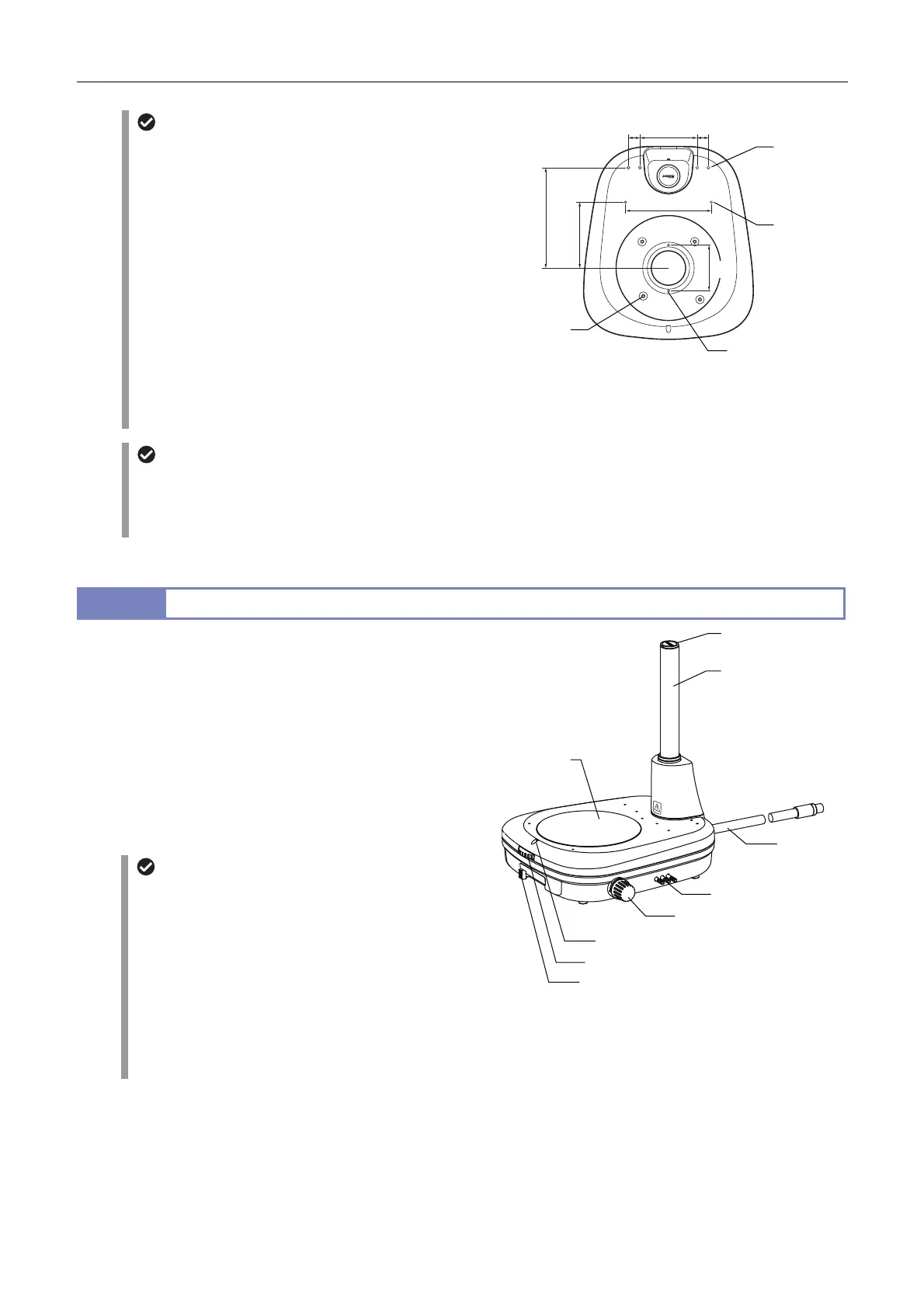
Screw holes for attaching optional devices
The base’s top board has screw holes for attaching various
devices. Screw holes (2) to (4) do not go right the way
through to prevent liquid penetrating into the base.
(1) 2-M4: Positioned under the stage plate attachment
part of the base. Usable for multiple
purposes. Used for attaching a C-TRS
Tilting Stage.
(2) 4-M6: Positioned under the stage plate attachment
part of the base. Used for attaching the
P-SXY64 XY Stage.
(3) 2-M4: Positioned at the center on the top surface
of the base. Usable for multiple purposes.
(4) 4-M5: Positioned at the rear on the top surface of
the base. Used for attaching a C-FDF
Flexible Double Arm Fiber Illumination Unit
(via a C-FIDH Fiber Holder).
Screw holes for attaching optional devices
Exchange for a C-EP support
The support length is 145 mm longer than standard when
the original support pillar for this stand is exchanged for a
C-EP support pillar. This is useful for attaching the focus
mount to a high position.
12.2
P-DSF32 Fiber Diascopic Illumination Stand
The P-DSF32 is a stand equipped with diascopic illumination
optical systems and the focus mechanism of the support pillar
vertical movement type.
ttach a C-FMCN Focus Mount to the support pillar.
The base with a large glass plate (180 mm dia.) enhances
usability and enables easier observation of samples in a containe
such as a petri dish.
The base has three indents for holding the base: on the right and
left planes and the rear plane.
dedicated hex driver is located at the top of the support pillar.
P-DSF32 Fiber Diascopic Illumination Stand
Sliding mechanism of the stage plate
The sliding parts are mounted on the base part for mounting
the stage plate, which can be slid by loosening the stage
plate fixing screw. There is a clearance gap of
approximately 3 mm around the stage plate when the stage
is securely set. The stage plate can be smoothly and finely
moved within the clearance gap by loosening the stage
plate fixing screw.
This mechanism is useful for positioning, especially for
high-magnification observation.
Securely fix the stage plate in place using the fixing screw
when this mechanism does not need to be used.
Illumination on/off, brightness adjustment
Attach the C-FLED2 LED Light source for fiber illuminator as the light source to the rear side of the base using a fiber.
Turn the illumination on/off and adjust the brightness using the C-FLED2. For details, refer to the instruction manual
supplied with the light source.
(1)
2-M4
(4)
4-M5
Depth 7
(3)
2-M4
Depth 6
(2)
4-M6
Depth 8
20 100 20
150
80
175
115
Driver
Fiber
Focus dial
Filter IN/OUT lever
OCC adjustment knob
Condenser lens switching lever
Support pillar
Stage plate fixing screw
Stage
plate
 Loading...