42 - FORM NO. 56043088 / Advenger
™
/ BR 600S, 650S, 700S, 800S
SQUEEGEE SYSTEM
SQUEEGEE SYSTEM LIFT MOTOR OVERVIEW
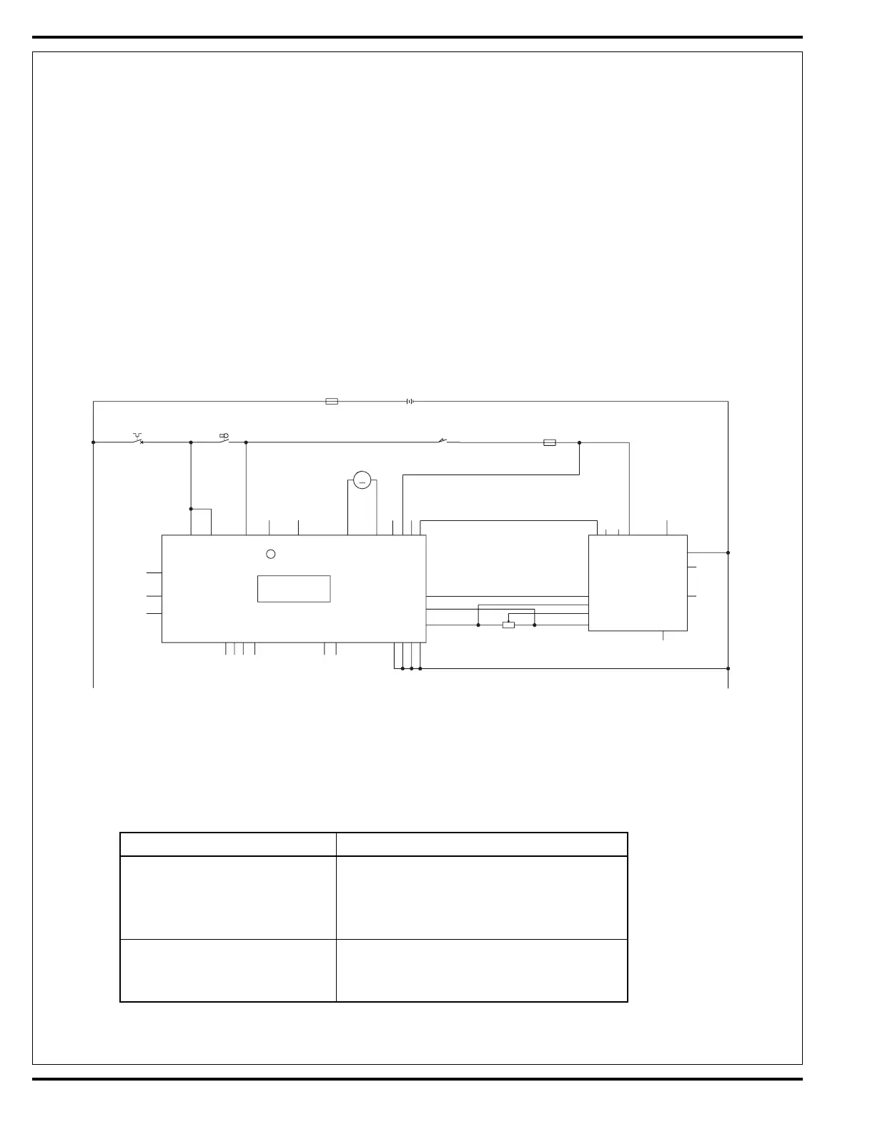
See Figure 2. The squeegee pickup tool is raised and lowered by a 36V actuator motor assembly mounted horizontally in the center rear of the
chassis underneath the recovery tank. The main control board assembly E1 regulates (manages) the machine’s squeegee tool system input and
output operating functions. See the Know Your Machine section in this manual for a detailed description of vacuum/squeegee operation modes.
OPERATIONAL OVERVIEW OF THE SQUEEGEE LIFT MOTOR REVERSE FUNCTION
During normal machine scrubbing the squeegee operates in the auto mode. To prevent squeegee blade damage and excessive wear the squeegee
tool is automatically lifted from the fl oor any time the machine is operated in reverse. See Figure 1. To get the squeegee tool to lift in reverse the
drive pedal must be moved off its neutral or forward position, which triggers the needed reverse A1 speed control output pin # 16 (Blu/Blk wire).
This (-) battery ground connection delivers the required E1 board input to the J4 connector pin #4 (Blu/Blk wire). This then activates an internal
relay circuit that outputs the correct voltage polarity for the M2 squeegee lift motor to run a specifi ed time (output from J3 connector pins #2 & # 3).
This raises the squeegee off the fl oor to the back up position, which is half of the normal distance observed when in the machine scrub off mode.
Moving the drive pedal back to the neutral/forward position opens the A1 throttle reverse output and the E1 control board loses its battery ground
signal. The J3 connector output reverses the polarity and lowers the tool back onto the fl oor.
Squeegee Lift Motor Operation
Problem Possible Cause
• Lift Motor runs in both directions • Threads in the moveable lift
but does not raise or lower the motor assembly drive tube are
squeegee tool assembly damaged (stripped)
• Lift cable damaged (stretched or broken)
• Lift motor does not run and the • Lift Motor Electrical system failure*
hourmeter/Status display shows
an error fault code (05, 19, or 20)
*Reference the main control board troubleshooting guide in the Electrical System of this manual for specifi c fault descriptions & service repair
actions.
FIGURE 1
* Programming Note: The Squeegee raise in reverse time period is adjustable. See the instruction in the Electrical Special Programming manual section to change
the distance the squeegee will raise in reverse.
TROUBLESHOOTING
M2
SQUEEGEE LIFT
ACTUATOR
M
S2
SW, SEAT
21
BT1
BATTERY, 36 Vdc
F1
S1
SW
SPST KEY
F3
F4
R1
POT. 5K OHM
1
2
3
RED
RED
BLK
RED
BRN/YEL
BRN/YEL
BRN
BLK/YEL
WHT/GRN
GRA
VIO
BLU/BLK
BLK
BLK
BLK
BRN
ORN
ORN ORN
VIO
YEL
YEL
B+ 1
B+ 2
KEY SW.
SEAT SW.
POT. OUT
POT. IN
REV.
PIN 13 -- POT. LO
PIN 3 -- POT. HI
PIN 4 -- POT. WIPER
PIN 16 - REV. ALARM
B+
B-
M2
M1
PIN 8 -- SLOW/FAST
B- 1
B- 2
B- 3
B- 4
A1
SPEED CONTROLLER
INTERFACE
THERMISTOR
E1
CONTROL BOARD
SPEED LIM IT
J4-8
J2-5
J3-5
J3-6
J2-7
J2-6
J2-10
J3-3
J3-2
J4-11
J4-4
J4-9
J4-3
PIN5 -- KSI
J2-9
PIN 18 -- SPEED LIM IT
GND
21
+
2121
+
21
 Loading...